

Author Archives: m150097
It’s a bird! It’s a plane! It’s.. MagLev!
Earlier this year, we heard about the world record on fastest train being broken by the Japanese bullet train. And yes, as you could have guessed from the title, it’s a maglev train! The train reached a record speed of 590 kilometers per hour on a test track which don’t use metal tracks. They float nearly 10 cm above special guideways, allowing for frictionless movement and work by using magnets to push the train away from the tracks and drive the train forward.
But how does magnetic levitation work? And what is its link to MO theory?
We have learnt that by drawing MO diagrams, we can determine the magnetism of a material – paramagnetic or diamagnetic. Apparently, diamagnetic materials are imperative in magnetic levitation.
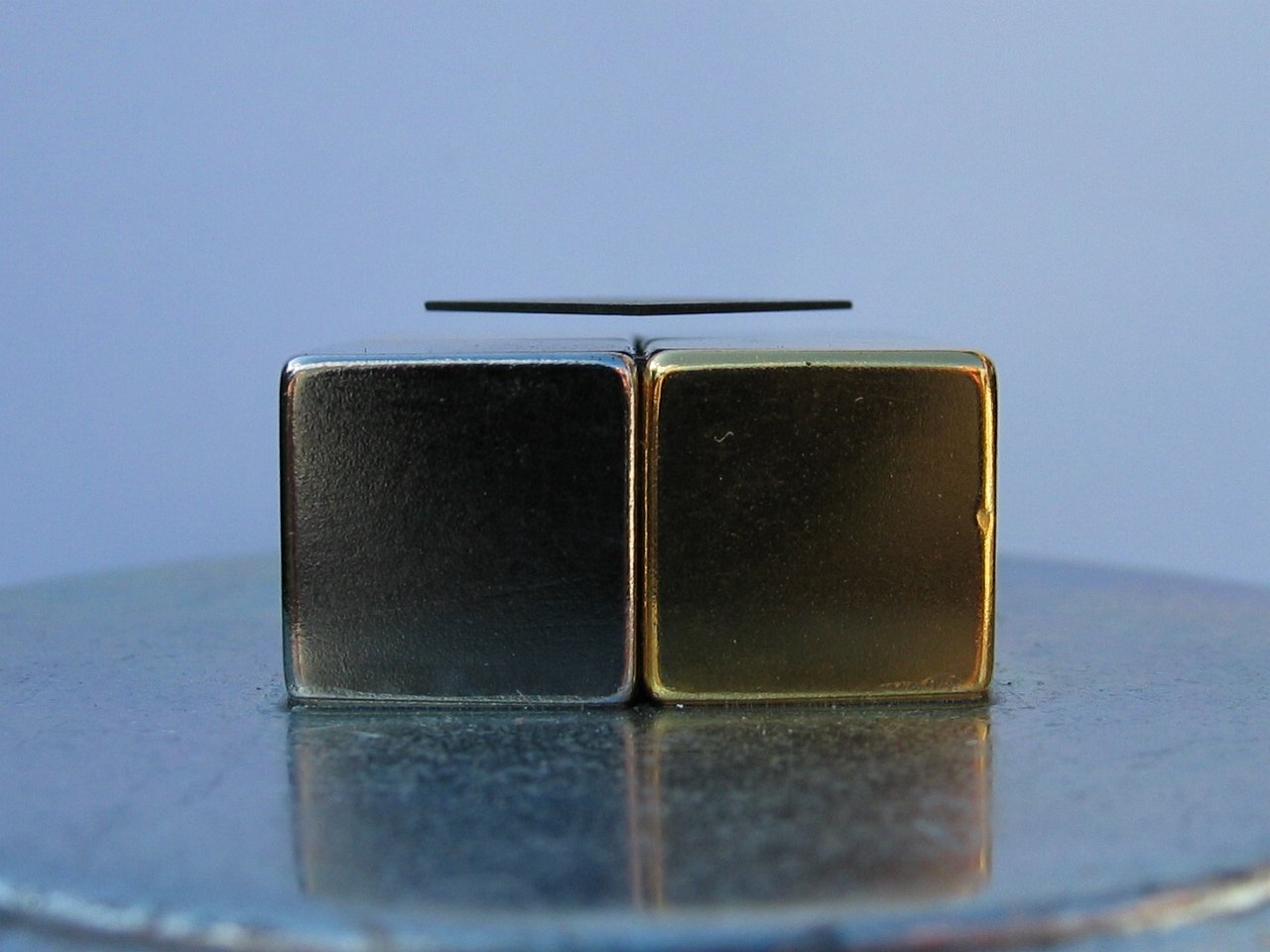
Stable levitation with permanent magnets was proven impossible by British mathematician Samuel Earnshaw in 1842 in his Earnshaw’s Theorem which states that a collection of point charges cannot be maintained in a stable stationary equilibrium configuration solely by the electrostatic interaction of the charges. Imagine putting permanent magnets on top of each other with their like poles meeting. They do indeed repel but will not float – the top magnet will simply slip aside and fall. Unless we put walls over the magnets to prevent slipping, the magnets won’t float.

In the picture above, the stick acts as the axis of stabilization to prevent the ring magnet from slipping. Without the stick the magnet will not float.
That is why diamagnetism is the key to magnetic levitation, as they provide the extra stabilizing force needed. Diamagnetic materials are materials which induce a weak magnetic field in the opposite direction when exposed to a magnetic field. They thus repel, and are repelled by a strong magnetic field. Generally, however, this repulsive force is not strong enough to overcome the force of gravity on the Earth’s surface. To cause diamagnetic levitation, both the diamagnetic material and magnetic material must produce a combined repulsive force to overcome the force of gravity.
One way to do this is by placing a diamagnetic material in a strong magnetic field. A thin piece of pyrolytic graphite (a diamagnet) is placed over a strong rare-earth magnet. The pyrolytic graphite is levitated above the magnet.
Another way to do this is by placing a magnetic material in diamagnetic fields with a biasing magnet. A permanent magnet is placed in the field of an electromagnet, and stabilized by diamagnetic plates put above and below the magnet. The magnet is levitated at a point far below the electromagnet where it is stable horizontally, but vertically unstable. The diamagnetic plates above and below stabilize the vertical motion.

The figure above shows the setup with the magnet levitated 2.5 m below an unseen 11 T superconducting solenoid stabilized by the feeble diamagnetism of fingers (x’1025). The magnet here is Ni-Fe-B which is a very strong rare-earth magnet. If a stronger diamagnetic material such as graphite is used for vertical stabilization, the levitation can be accomplished with common permanent magnets.
So why be a magician and do the trick by illusion when you can be a chemist and accomplish this for real? ;p
Wave Functions and Nodes
The properties of an electron can be described by a mathematical function called wave function (ψ). There is a radial and an angular part of every wave function. As the radial wave function changes sign from positive to negative, it crosses the x-axis and that point where ψ=0 is called a radial node. Angular nodes can be found by looking at the 3D diagram of the atomic orbitals. An angular node exists in a plane where the electron density is zero. For example,

This is an s orbital. It has no angular node as all the planes intersect the orbital.

These are p orbitals. They each have one angular node, which occurs on the plane which doesn’t touch the orbitals i.e. xy plane for 2pz, yz plane for 2px and xz plane for 2py.

These are d orbitals. They each have two angular nodes, again occurring on the plane that doesn’t touch the orbitals, i.e. yz and xy planes for 3dxz, xy and xz planes for 3dyz, xz and yz planes for 3dxy, planes bisecting the xz and yz planes for 3dx2-y2 and for 3dz2 are the two cones in the z axis facing in opposite direction with their vertices meeting at the origin, as shown in picture on the right
The total number of nodes (angular + radial) is equal to n-1, where n is the principal quantum number. Hence,
1s orbital has no angular no radial node
2s orbital has no angular node and one radial node
2p orbitals have one angular node and no radial node
3s orbital has no angular node and two radial nodes
3p orbitals have one angular node and one radial node
3d orbitals have two angular nodes and no radial node
and so on.
Therefore, by knowing the 3D shapes of the orbitals and therefore the number of angular nodes, we can find out the number of radial nodes the orbital has, which corresponds to the graphs below.

Molecular Orbitals – part 1
Molecular orbitals resulting from combining atomic orbitals can be constructed in phase (ψ+) and out-of-phase (ψ-). In phase addition occurs when the wavefunctions of the two atomic orbitals combined are of the same sign. For example, in the simplest case of 1s AO which is positive, adding two such AO will lead in a constructive interference. A bonding MO is thus formed. Similarly subtracting the AOs leads to a destructive interference forming an antibonding MO.
In the region between the two nuclei in in phase addition the value of the MO wavefunctions is greater than that of the AO wavefunctions. Thus it is more like likely to find an electron in the inter-nuclear region.

The in-phase MO is lower in energy than the isolated AOs because:
1. When the MO is occupied, there is increased electron density between the nuclei. The attraction from both nuclei leads to a lowering of the potential energy of the system.
2. An electron in in-phase MO is less constrained compared when in an AO (i.e. it is more delocalized) leading to a decrease in its kinetic energy.
The in-phase combination MO is lower in energy than the original AO and occupancy of this orbital gives rise to bonding, thus this orbital is called the bonding molecular orbital.
For the out of phase addition, the anti-bonding combination has a node – where the electron density is zero. This is shown by the crossing point on the x axis (horizontal line).


The out-of-phase MO is higher in energy than the isolated AOs because:
1. When the MO is occupied, there is much more electron density outside the inter-nuclear region than in between the nuclei pulling them apart from each other. The potential energy in this MO is therefore higher than in the separate species.
2. The out-of-phase MO contains a node. This means that the kinetic energy of the electron in this orbital is greater than when it is in either the AO or in-phase MO.
The out-of-phase combination MO leads to an increase of the energy with respect of the original AO, thus this orbital is known as the anti-bonding molecular orbital.
This can be summarized graphically using an energy level diagram:

Molecular Orbitals – Part 3
As described in Part 2, the filling up of molecular orbitals follow the same principles and rules as filling up atomic orbitals. Now, we can use energy level diagrams to rationalise differences in the stability of molecules. Let us look at the molecules H2+, H2, He2+ and He2
The molecular orbitals would look like:

The table below shows the electronic configurations, dissociation energies and bond lengths of the respective molecules.

MO theory helps us explain the difference in the dissociation energies of the molecules. H2+, H2 and He2+ are stable with respect to their dissociation into their constituents because they have more electrons in the bonding MO than the anti-bonding MO. He2 however has two electrons in the bonding MO and two in the anti-bonding MO. The anti-bonding MO is raised more in energy than the bonding MO is lowered, so we can expect the two anti-bonding electrons to outweigh the two bonding ones. As a result, He2 is unstable and will dissociate into He atoms.
We have discussed the concept of bond order in the previous post. The bond order can also be considered when determining whether a bond forms (i.e. whether the molecule is stable). For example,
H2+ has 1e in bonding, 0 in anti-bonding –> bond order = 1/2
H2 has 2e in bonding, 0 in anti-bonding –> bond order = 1
He2+ has 2e in bonding, 1 in anti-bonding –> bond order = 1/2
However He2 has 2e in bonding, 2 in anti-bonding –> bond order = 0. Therefore it is unstable
Aromatic Systems
The advantage of MO theory becomes more apparent when we think about π bonds, especially in those situations where two or more π bonds are able to interact with one another. Some of the delocalized molecular orbitals that result will be stabilised, while others will be destabilised.
Let us first consider the π bond in butadiene using MO theory.

From valence orbital theory we might expect that the C2-C3 bond in this molecule to be able to rotate freely since it is a sigma bond. Experimentally, however, it is found that there are significant barriers to rotation about this bond. It is also found that the entire molecule is planar. The C2-C3 bond, while longer than the C1-C2 and C3-C4 double bonds, is also significantly shorter than a typical carbon-carbon single bond.
These observations can be attributed to the concept of delocalized π bonds. The four p orbitals are all parallel to one another, and thus there is π-overlap not just between C1 and C2 and C3and C4, but between C2 and C3 as well. The 4 atomic orbitals have combined to form 4 π molecular orbitals.
In the π system, there are no degenerate MO i.e. all MO will be in different energy levels. Thus we will have 4 MOs, all with different energy levels.
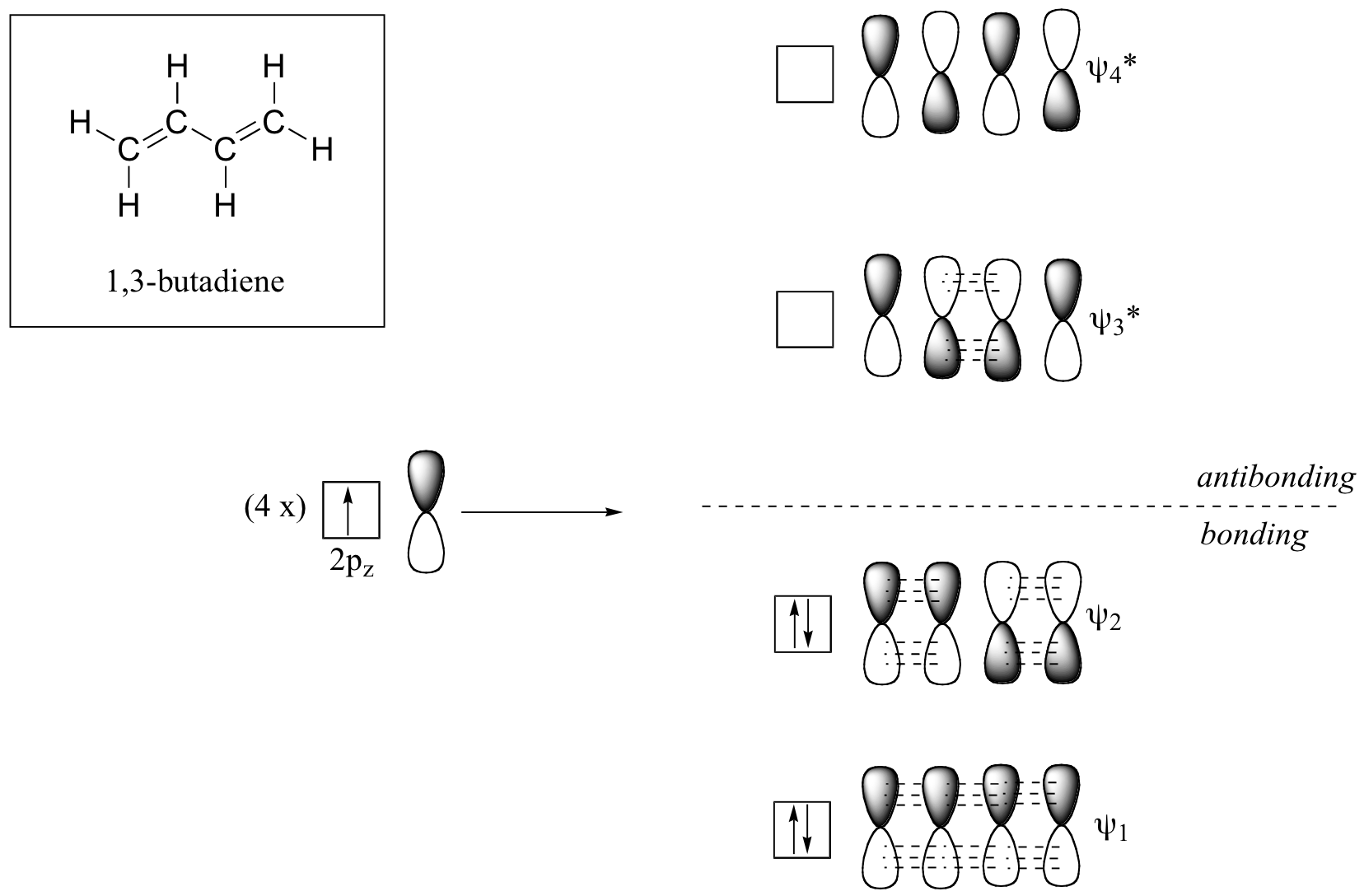
The lowest energy molecular orbital, Ψ1, has zero nodes, and is a bonding MO.
Slightly higher in energy is the Ψ2 orbital. This orbital has one node between C2 and C3, but is still a bonding orbital due to the two constructive interactions between C1-C2 and C3-C4.
The two higher energy MOs are denoted Ψ3* and Ψ4*, and are anti-bonding. The energy of both of these MOs is higher than that of the AOs of which they are composed.
Ψ3* has two nodes and one constructive interaction.
Ψ4* has three nodes and zero constructive interactions.
Filling up the MOs with regards to Aufbau’s principle, we will get 2 pairs of electrons on the bonding MOs and no electron on the anti-bonding MOs. This gives us a bond order of ½(4-0) = 2. This thus corresponds to the number of π bonds that the molecule has!
Now, you might be wondering, how on earth are you supposed to come up with the MO diagram of the π system!? Fret not, there is a trick to this!
First, we draw out evenly spaced dot representing the positions of the atom (numbered 1 to 4).

Then we add two extra atomic positions – one dot to the left of 1 and one dot the right of 4 numbered 0 and 5. There are no atoms here but these are necessary for the graphical constructions of the desired MOs.
![]()
Then, draw a half sine wave is between the positions 0 and 5.

The contribution of each AO to the MO is given by the height of the sine wave at the position of that atom.

Similarly, all the other three MOs can be deduced this way. The MO above gives the MO with lowest energy, and it has zero nodes. With increasing energy the number of nodes increase, i.e. the next MO will have 1 node, and the one after that will have 2 nodes, and so on. The MOs for the π-system is shown below:

With this method, the MOs for a π-system composed by any number of p-orbitals can be predicted. 😀
Now, to determine whether a π MO is bonding, non-bonding or anti-bonding, we have to see whether there are more constructive or destructive interactions. Let us take a look at the above example.
For 1π, all interactions are constructive, hence MO is bonding.
For 2π, 2 interactions are constructive (between positions 1 & 2 and 3 & 4) while one is destructive (between positions 2 & 3). Hence MO is bonding.
For 3π, 1 interaction is constructive (between positions 2 & 3) while two are destructive (between positions 1 & 2 and 3 & 4). Hence MO is anti-bonding.
For 4π, all interactions are destructive, hence MO is anti-bonding.
Note that when there is an odd number of MOs, the MO with equal number of constructive and destructive interactions will be non-bonding.