After some discussion, we decided to change the design of the dispensers entirely, due to the following reasons:
- after the visit to the farm where we were able to finally get a


After some discussion, we decided to change the design of the dispensers entirely, due to the following reasons:
This would be the last step of closing the loop — an automated dispenser that will release solutes when the water characteristics has met the allocated thresholds.
When we approached the design of the dispenser, we were certain that we wanted it to:
We were given the idea by Hanyang (thank you!) of the Archimedes Screw.
Upon further expansion on the inspiration given, we came up with the idea of installing a motor and an Arduino to the end of the dispenser to be able to pick up signals sent to it and will start winding up the solutes, into the water. It will stop dispensing only when the sensors have picked up that the water characteristic is back to its normal level aka back below threshold.

Today, 19/07/2022, marks the day that we have been preparing so hard for.
Live. Testing.
We managed to fix all problems regarding our buoy the day before (with a lot of praying).
When we reached the site, we had a quick chat with the R&D Manager, whom we have been in touch since just about the start of our project.


Currently, there is only one active aquaculture farm in QianHu and it is for prawns. We were allowed to test our device for 4hrs there (we were lingering around the area for the whole duration) and everything went well (must be because of all our praying). During that time, we managed to get to know more about the industry problems and aquaculture in general.
GENERAL NOTES:
1. Massive deaths in fish farms happen very often. The reason is due to fluctuating water quality (pH, turbidity..) which causes the fish to get stressed. And when they are stressed, they fall sick. And when a few fishes fall sick, the entire pond suffers as the sickness spreads quickly.
2. They want floating sensors for fish farms. Most sensors sold in the market sink to the ground. Aqualoop floats!
3. The current system costs a few thousand dollars. And they have to keep changing sensors every 6 months – 1 year for maintenance. Each sensor head costs hundreds of $$. Aqualoop can help cut costs by being modular, open-source, and economically efficient.
4. It is only viable to have expensive sensors such as the ones Qian Hu is using ONLY if a farm has 20 ponds or more. This isn’t exactly an efficient thing because if we want to increase food production by 2030, the farms have to be distributed and decentralized. Aqualoop can help this by being cheaper; therefore allowing more farms to be built on small scales.
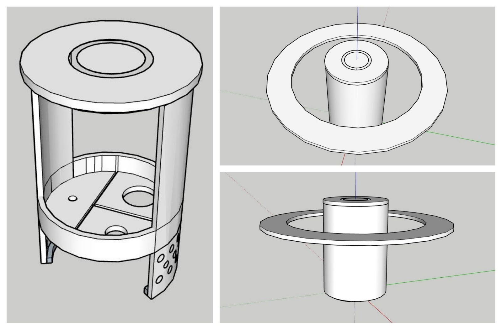
Tackling the main compartment was one of the most crucial part of the device, which we worked on & off throughout the whole design process, since it hold all of our electronic devices and sensors. We wanted everything to have a snug, not tight, fit so that it will be able to handle any motion be it abrupt or gentle and the parts will not collide with each other inside this compartment.


Screwing in the main compartment into the buoy, this is how it turns out. We also designed a tumbler sort of disk attached to the bottom of the main compartment to insert the sensors in and to ensure that it does not move around too much. The sensors will end up being extended past the main compartment into the protective barrier in the bottom (refer back to the main overview for a better idea).


After placing in the Arduino board and the batteries in their relative compartments, this is how it looks like. Everything fits! (YAAAS)


After some behind-the-scenes testing of prototypes, we decided to add a ring of LED lights around the top of the device to allow for easier debugging and testing by the user when problems eventually come up.
Previously, we found difficulty finding out the problems unless directly connected to the Arduino and reading off from the console. When testing the device on-site, we cannot ensure the device is appropriately working without checking the cloud server.
With the installation of the LED, it allows for easier checking of the device when doing long-term testing. If there is any error in the program bootup, the LED will turn red signaling something is wrong. This can help us, while testing, to see if any connections are missing or if the code is wrong. The LED also shows progress of the code being processed. Colorful lights mean the boot up is successful.
The LED will shine a solid ring of light that shows the progress of taking data samples and transferring it


After we were done with the main body, we moved on to tackle the main code of the device. To get a better picture of how we wanted the circuitry to look like, we first drew a general sense of the circuitry (as shown below). We then went ahead with the coding.

After much testing, everything was finally running smoothly and we designed two PCBs and printed it to fit everything in our body. One of the PCB works to connect the arduino and the sensors, and the other is to connect it to the antennae for the communications system.

We catered more than a week’s worth of time to this stage of our designing as we wanted all the pieces to be snuggly fit. This is to prevent any damage to the fragile sensor due to abrupt motion.
Due to our poor time estimation, we may have ordered the electronic parts a little too late, so all the design work had to be done without the exact measurements of the parts any than those that were provided on the pages that we ordered them from. So…fingers crossed and let’s hope that everything fits right.
Our contingency plan, for if the compartments are too tight, is to use a soldering iron to hopefully be able to heat up the acrylic enough to compress the sides enough to fit the parts in. If the compartments turn out too large, we will just have to glue (one that is aqua-friendly) the parts to the compartments.
I will be breaking down the individual interior parts in more detail in the next few posts. For now, enjoy the curated gallery!


We have finally settled on a shape to maintain buoyancy, portability and modularity. Through our knowledge from past modules and observations, we tried to keep the centre of gravity underneath the centre of buoyancy to keep the object unconditionally stable. We will place most of the heavy components like the battery and sensors near the bottom to achieve this.
We will be using the color yellow as it symbolizes special markings at sea.

From our first prototype, we improved our device with the goal of making it more modular and serviceable. We approached it by breaking up the main compartment of the buoy into different components, thereby it more accessible. This can be seen in the picture on the right where each section has its own functionality.
We keep the general shape of the device similar to our first prototype since it was able to stay buoyant. We added a protective barrier at the bottom to keep the sensors safe from any nibbling by the fishes.
Our general idea for our first design is to keep it simple. We needed something that was able to tackle our main issue which will be the buoyancy and stability of the whole buoy. On top of that, a large enough component that is able to hold our sensors and devices that we want to be deployed in the tank. While doing so, we needed to keep in mind to keep its footprint compact since we were told that every volume is valuable to industry companies.
We did some sketching and this was what we had came up with. Our very first iteration that is able to tick our checklist. We have designed a case (as seen in the left photo) that is able to house all of our components snuggly, in a space as compact as possibly.
After running the case in a SOLIDWORKS stimulation, we found that it was far from buoyant and decided to add a ring to rectify this.
This resulted in the finalized first design as seen in the pictures on the right.