Given none of us had any prior drone flying knowledge, much less hardware knowledge, coming out with our drone design was not easy. Nevertheless, after much brainstorming and research, we finally produced our own blueprint for our drone!
Initial Phase
When we first commenced our project, we decided on using the Skysurfer2000 as our glider drone (as advised by our mentor Kanesh).
Preliminary sketches of our drone set-up and fuselage layout
Prior to the arrival of our materials, we depended on online dimension to sketch out a preliminary blueprint. Initial calculations also led us to believe that a 350g balloon would be sufficient to lift our entire system. However, when the drone arrived, we realised that the fuselage space of the Skysurfer2000 was indeed insufficient to fit our entire payload (cutbox mechanism, pixhawk, GPS etc.)

Insufficient space in the Skysurfer2000 fuselage
Prototype
In response, the team decided to order a new drone – the ZETA Sky Observer – that has a huge cylindrical belly as a fuselage. The new drone would provide us with ample space to fit our payload, with a fuselage door for easy customisation. However, as the drone would take weeks to arrive, we decided to build our prototype with the Skysurfer2000 first.
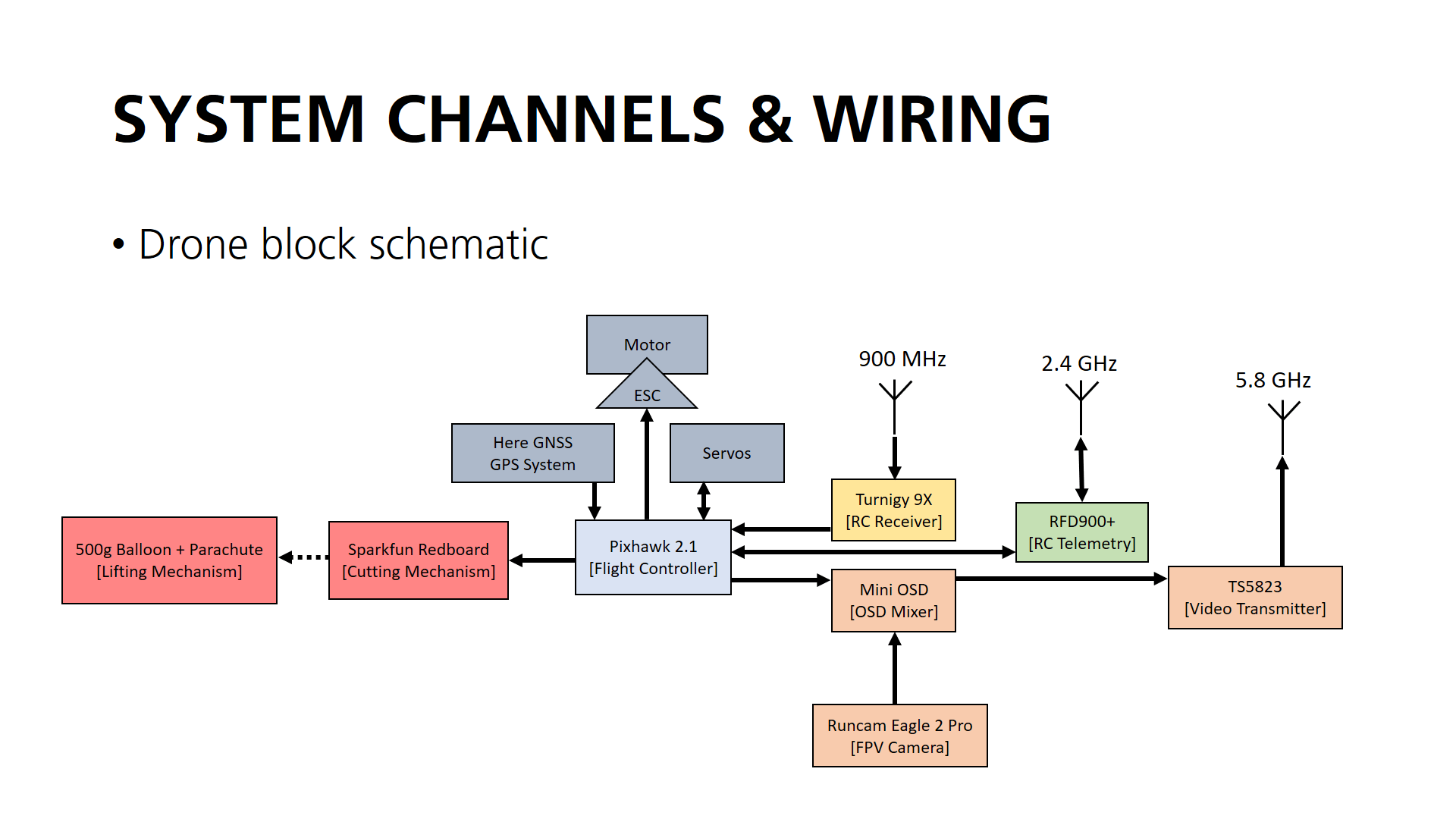
Further reading into drone system wiring led us to come up with channel and wiring plans for our drone, seen below.

The different radio frequencies we used as well as their respective functions. Depending on where we are conducting our tests, different antennas will be used to ensure we maintain communications with the drone at all time.
 Our drone block schematic, which shows the main connections within the fuselage

Final Product

Front view of our ZETA Sky Observer with our FPV camera


