We have decided to go ahead with the slider design for our exoskeleton.
Figure 1: Recap of Slider Design
In order to further prototype with this design, some preliminary calculations had to be done to ensure that Parts 1 and 3 do not collide when the finger is fully extended.
We can model our fingers as seen in Figure 2 below. When our fingers are flexed by an angle of θ, the two bodies of the device, represented by the white rectangles, move away from each other. Note that when the two bodies move away, they still have to remain connected to each other. Thus, the total length of the device increases when the finger is bent, similar to how our skin is stretched as our fingers flex.
Figure 2: Modelling of our fingers
This means that our device must be able to increase in length when it is flexed (which is the reason behind all our preliminary designs). Thus, we can calculate the full length of the device when the finger is fully bent. In Figure 3, by adding some additional length to the bodies, and a circular shape to represent the hinge, we can properly model how the slider should look when the the finger is fully bent. In the model in Figure 3, the increase in length from one device part is represented by the green length and has been denoted by a ‘?’.
Figure 3: Modelling the Slider and the increase in length
However, when the finger is fully extended, this increased length (denoted by green) has to be ‘hidden’, by moving along the track towards the centre of the middle piece (part 3). Thus the middle track has to accommodate the additional lengths from both Part 1 and Part 3. We attempt some preliminary calculations based on this model to find a formula for the sum of these additional lengths to determine if our mechanism is feasible.
With some basic trigonometry, we can find this green length in terms of r. which is half the height of the device.
Figure 4: Breakdown of the shapes used in calculations, with relevant lengths used in calculations labelled.
Length needed to be hidden,including radius of wheel=2r tan(θ/2)-x
Let r = radius of circle, 2r = thickness of device
Angle ϕ =(180-θ)/2 by some geometrical calculationst = r sinϕ
s = t/cosϕ = (r sinϕ)/cosϕ = r tanϕ
r – s = r(1 – tanϕ)
a = cosϕ(r – s) = r(cosϕ – sinϕ)
x = (r – s)/tanϕ = r (cosϕ/sinϕ – 1)Length needed to be hidden = 2r tan(θ/2) – x
2r tan(θ/2) – x = 2rtan(θ/2) – r(cosϕ/sinϕ – 1)
=2rtan(θ/2) – r(cos(90-θ/2)/sin(90-θ/2) – 1)
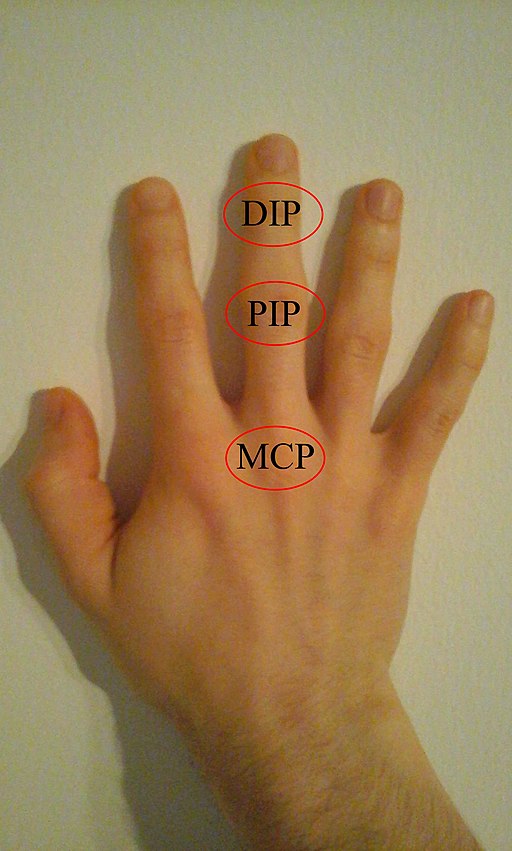
As a single finger is made of multiple joints, the joints will be referred to their acronyms, DIP, PIP and MCP. The corresponding position of these joints are illustrated in Figure 5, from Kohlins [CC BY-SA 4.0 (https://creativecommons.org/licenses/by-sa/4.0)].
Figure 3: Modelling the Slider and the increase in length
Figure 5: DIP, PIP and MCP joints of the finger
We found finger joint angles from literature for our calculations. We primarily used data for stroke patients from Carpinella et al., 2011, seen in Table 1. However this is missing the DIP value, thus data from a normal patient’s hand is used from Hume et al., 1990.
Thus the set of angles we used:
θ MCP finger = 116°
θ PIP finger = 95°
θ DIP finger = 120°θ MCP thumb = 90°
θ IP thumb = 140°
Table 1: Stroke patient finger joint angles.
To calculate the middle part of the device (part 2), we look at the angles for DIP and PIP, which are the joints the flank the middle part of the finger. Thus, substituting in the relevant θ values, we find:
For DIP,
θ = 120°
Length needed to be hidden = 3.886751 rFor PIP,
θ = 95°
Length needed to be hidden = 2.2662858 rSum of length = 6.1530368 r
Thus, the middle part must be able to at least accommodate the sum of these lengths, while maintaining a short enough length so that its integrity is not undermined. That is to say, it must be at least as long as the sum of lengths. Yet, it must be long enough to cover the length of the actual patient’s middle part of the finger. However, the chosen value of r must also be big enough to accommodate the size of our hinge.
In the end, we chose r = 3 mm, which is enough to accommodate our screw of radius 1 mm.
Literature used:
Carpinella, I., Jonsdottir, J., & Ferrarin, M. (2011). Multi-finger coordination in healthy subjects and stroke patients: a mathematical modelling approach. Journal of neuroengineering and rehabilitation, 8(1), 19.
Hume, M. C., Gellman, H., McKellop, H., & Brumfield Jr, R. H. (1990). Functional range of motion of the joints of the hand. The Journal of hand surgery, 15(2), 240-243.


