Chinese Rescue Approved!

It as been a couple of days since unavailability of parts on HobbyKing halted progress on our drone. Though the possibility of obtaining the items we need on Taobao was always lurking in the corner, we were reluctant to do due to different people telling us different things regarding claiming from NTU. (Tony said that when he attempted to do so a while back his claim was rejected, whereas Dr Ho vaguely remembered that groups in previous years had successfully claimed for purchases on Taobao)

We also made our trailblazer order consisting of small, inexpensive items from Taobao to try our luck claiming. Should that go through, the million dollar question of whether or not we can claim from Taobao would be solved. Meanwhile, we also emailed Ms J to ask about claiming of items on non-English websites.

Big Hurrah!

Around a day after sending the email, two events happened in quick succession: our groupmate was summoned to a meeting regarding discrepancies in deducted amount between his bank statement and the receipt issued by Taobao. This was enough evidence to show show that contrary to what Tony said, we indeed could place our orders off Taobao!

Not long after, Ms J also replied to our email query:

Hurrah! We're through!

Taobao Approved!

Now comes the mad scramble to get our parts ordered and delivered as soon as possible!

Communication Protocols

In a previous post, we examined the different options we had (Layer 3 in the OSI Model) for transmitting data.

We’ve focused our efforts so far on working with ESP-NOW for a few reasons:

  1. ESP-NOW does not require devices to be connected to the same Wi-Fi network
  2. TCP has overheads (eg handshakes) which we do not fully need.

Working with UDP would allow us to customise the later protocols to suit our needs, but UDP is still built for communication over an IP network.

ESP-NOW suits our use case perfectly:

  1. Devices do not need to be connected to the same Wi-Fi network
  2. Conceptually, it performs the same higher-throughput-no-features role that UDP does
  3. ESP-NOW supports basic encryption
  4. ESP-NOW has built-in error detection
  5. ESP-NOW supports basic re-transmission of packets that are not received

Our application has the following requirements:

  1. Guaranteed, in-order transmission of files
  2. Ability to discover available files on a remote node
  3. Ability to resume transmission from an arbitrary offset in a file

With these in mind, we implemented a modified version of the Trivial File Transfer Protocol (TFTP). TFTP is a very simple protocol used in resource-constrained environments which makes it particularly suitable for our application. Customisations:

Window Size: We implement the Window size option. TFTP’s default behavior of acknowledging every data packet is known to affect throughput. Acknowledging multiple data packets at a time improves throughput.

Binary Packing: TFTP’s use of ASCII strings is inefficient, limiting how much information we can pack into a single packet in certain situations. We opt to identify files by a number as filenames are not important in our application.

File Offsets: Read requests specify not only the file index, but also the offset at which to start transfers at. This will allow resuming of data transfers (eg the UAV goes out of range).

The work-in-progress implementation discussed above can be found here. A test project integrating both client and server together can be found here.

Aircraft Parts Purchase: Attempt 1

Parts Approval: Attempt 1

Banking on our past experience with remote controlled aircraft, we came up with a parts list containing the following:

Our first attempt at going to Kanesh for approval

This was sent to Kanesh (a senior who is now running his own show and is assigned our mentor) to review.

Parts Approval: Attempt 1 Results

After around 3 days, Kanesh came back with the verdict. Overall, he was alright with the parts just that he strongly recommended that we use the Turnigy 9x, as there are sufficient online resources (manuals/videos) for setup/calibration/troubleshooting. Acceding to this request, we altered the parts list accordingly:

Second run after Kanesh's recommendations

Roadblock! $$$ Concerns!

After gleefully adding our items to the Hobbyking cart, we we going to checkout, eagerly expecting shipping to be cheap yet fast. Little did we expect to be greeted by a three figure shipping amount!

Rude surprise!

We were in for a rude surprise upon checkout!

Alas, we were told by Kanesh to hold our order; he will try to purchase the items for us using his account banking on the hope that his HobbyKing VIP status might grant him a substantial discount.

Just like that, our progress on building the drone has grinded to a halt: grand plans of spending the next week having bonding time in the lab building and flying the Bixler were shelved.

ESP-NOW Data Transfer

After realising the need for faster data transfer, we started looking at the ESP32 and the various protocols it supports. Although using layer 4 protocols like TCP or UDP is possible, the overheads of handling connections to an ad-hoc network could be problematic. We thus examined ESP-NOW, a protocol defined by Espressif which sends data over raw 802.11 packets directly without the need for devices to be on the same WLAN network.

Packet Capture of ESP-NOW data being sent and the resulting acknowledgement packets

Code was written to test the effects of the following parameters on the throughput of ESP-NOW:

  1. Wi-Fi Data Rate
  2. Broadcast or Unicast:
    1. Sending packets directly to a peer identified by their MAC address results in the peer sending an Acknowledgement packet back
    2. Broadcasting packets (send to MAC FF:FF:FF:FF:FF:FF) will not cause Acknowledgement packets to be sent, potentially speeding up transfer.

The test code transmits 250 byte (maximum supported packet length) ESP-NOW packets as fast as possible from a device (henceforth the master) to another device (henceforth the slave) for 3 seconds, sleeps for 10 seconds, then repeats.

The slave device then transmits the number of packets received at 1 second intervals back to the master device, which then prints out this number.

The following data rates have been observed between two ESP32-DevKitC’s approximately 1m apart in a standard household environment (ie with Wi-Fi interference):

Transmission Type Wi-Fi Data Rate Max Throughput Observed (bytes) in 1s
Unicast WIFI_PHY_RATE_1M_L 89250
Broadcast WIFI_PHY_RATE_1M_L 101000
Unicast WIFI_PHY_RATE_11M_L 349250
Broadcast WIFI_PHY_RATE_11M_L 497000
Unicast WIFI_PHY_RATE_54M 778500
Broadcast WIFI_PHY_RATE_54M 963000
Unicast WIFI_PHY_RATE_MCS0_LGI 442000
Broadcast WIFI_PHY_RATE_MCS0_LGI 502250
Unicast WIFI_PHY_RATE_MCS4_LGI 756750
Broadcast WIFI_PHY_RATE_MCS4_LGI 930750
Unicast WIFI_PHY_RATE_MCS7_LGI 224750
Broadcast WIFI_PHY_RATE_MCS7_LGI 706250
Unicast WIFI_PHY_RATE_MCS0_SGI 464750
Broadcast WIFI_PHY_RATE_MCS0_SGI 535000
Unicast WIFI_PHY_RATE_MCS4_SGI 771750
Broadcast WIFI_PHY_RATE_MCS4_SGI 945250
Unicast WIFI_PHY_RATE_MCS7_SGI 734250
Broadcast WIFI_PHY_RATE_MCS7_SGI 833500

We can observe that sending broadcast instead of unicast packets speeds up data transmissions slightly. Increasing the Wi-Fi bit rate also has a significant impact on data rates, but comes at the cost of significantly more packet loss (packets not acknowledged by peer).

Quick testing in outdoor conditions (ESP32-DevKitC placed at a distance of 20m with line-of-sight visibility) shows similar (or slight better) data rates at WIFI_PHY_RATE_1M_L and WIFI_PHY_RATE_11M_L when compared to the results above. Data rates of up to 549250 bytes/s were observed at WIFI_PHY_RATE_24M. Almost all packets were lost at WIFI_PHY_RATE_54M.

12 bit data sampled at 80Hz results in 553Mbit or 70875 kbyte of data, which would take approximate 145s to transmit at 500000 bytes/s.

These data rates were also observed using the on-board PCB antenna. An alternative option is to connect an external antenna to ESP32-WROOM-32U modules, which is likely to improve the data rate.

Fixed Wing Drone

Initially the team planned to use a quad copter to collect data from the ground sensor nodes. However due to range and efficiency, we have decided to use a fixed wing remote control plane to be the transportation tool.

Air frame Selection:

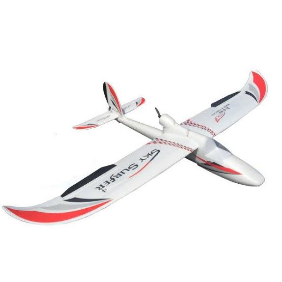
RC plane model that our team will be using for our first prototype will the Sky Surfer X8 with a wingspan of 1410mm. This plane model is a high wing trainer plane, high wing plane generally has low center of gravity which would promote good lateral stability. A plane would with good lateral stability would help to overcome side slip and correcting rolling moments. Which would be beneficial for first time RC plane flyers like us.

The Sky Surfer X8 is also a pusher plane, where the motor and propellers are mounted at the back the plane. There are various benefits from this configuration.

  • The propeller is well protected. In the event of nose landing or unfortunate crashes, the damage to the motors would be at minimal.
  • It would not obstruct the view of our FPV.

The EPO (Expanded PolyOlefin) material of the Sky Surfer also makes maintenance and repair easier.

Motor & Propellers:

The suggested configuration of the Sky Surfer X8 is a A2212 KV2200 brushless out runner motor paired with a 6 X 4 APC propeller. However, to increase the efficiency and thrust of the plane, we have decided to upgrade the motor with a Dual Sky ECO2814 (1330kV) brushless out runner motor paired with a 7 x 6 APC propeller.

However, the current airframe only support up to 6 inch propeller, hence we will be getting a motor mount to further enhance the performance of the motor by pairing the motor with a 7 inch propeller.

ESC:

Selection of ESC is based on our motor selection. Hence for the Dual Sky ECO2814 (1330kV) the suggested ESC in the datasheet the max current draw is at 36.9A. Hence the ESC chosen is a XRotor 40A ESC.

Servo:

The recommended servo is a 9g servo, however the servo that came with the kit is a plastic gear servo. Plastic gears servo are more likely to strip if the motor is jammed or overloaded. Compared to metal gear servo which are longer lasting. We then decided to go ahead with the EMAX 12g Metal Gear Servo.

LiPo:

Battery Capacity is mainly determined by the motor choosen. Hence, with reference to the datasheet of the Dual Sky ECO2814 (1330kV, we have decided to use the Turnigy nano-tech 2200mah 3S 35~70C w/ XT60.

Lipo Alarm:

The lipo alarm is a device to be plug into the lipo balance lead. It will release a “alarm” when the LiPo voltage falls below 3.3V.  Which is essential in notifying us when the voltage is low. 

Video FPV:

Spotter V2 attach with a build in transmitter of 5.8GHz

Posted in UAV

PCB Rev 3 Proposal

Following the previous electronics update, a few tradeoffs has to be made.

Battery Life

Taking measurements at high rates 100+sps requires the microcontroller (MCU) to be active most of the time. This has a large impact on the battery life of the device. For this reason, we will be using larger batteries which takes up more space. In addition, we will be using 18650 Li-Ion cells as they are more energy dense than the more common LiPo cells.

Size

The size of our datalogger will be relatively large, with the majority of the space taken up by the Li-Ion cells. As a result, we will not make an attempt to compact the PCB, and optimize for performance instead.

Instrumentation

Since we are moving towards research grade instrumentation, is more economical to have the sensor interface separate from the main MCU and data storage board. This allows us to design new interfaces for different sensors as needed without redesigning the costly MCU section.

Furthermore, this means that we can adapt the datalogger to accept any kind of sensors.

Proposal

Here we present the 3rd revision electronics.

As discussed, the PCB is broken into 2 parts – motherboard and daughterboard. 

At the heart of the motherboard is the ESP32, a MCU with a built-in WiFi transceiver. Stores data into a SD card and sends data over WiFi to the UAV as it flies past.

The purpose of the daughterboard is to power the various sensors and amplify the signal before sending it over to the Analog to Digital Converter (ADC) on the motherboard.

Analog signals are differential and sent over twisted pairs. This ensures that the signal is not affected by any nearby electromagnetic interference (EMI).

Lastly, the option of external power supply allows the operator to attach a high capacity battery (eg lead acid battery) for long term operation.

Printed Circuit Board (PCB) Rev 3

The original PCB was designed for low sample rate, long range transmission and long battery life.
However, these design goals have to change to accommodate for the new project specifications.

In this new PCB design revision, we will attempt to achieve:

  1. High Resolution (24 bits native, 22 bits effective)
  2. High Sampling Rate (<80sps)
  3. High Transmission Rate (noted in previous blog post)

Resolution

In order to achieve high resolution, the analog front end has to be carefully routed to reduce the effect of noise. For this reason, we will be using a differential Analog to Digital Converter (ADC). [Link to a paper by Microchip]

Sampling Rate

Sampling rate is limited by the speed of the ADC, data bus and internal storage medium. Sampling rates of more than 1ksps are possible, but we will be limited by the transmission rate as noted in the previous post.

Transmission Rate

Since LoRa was not designed for high transmission rate, we will be designing the new PCB around a WiFi transceiver, ESP32.

The Art of PCB Routing

When making analog or high speed designs, special care must be taken in order to reduce noise or error in the signals. There are a few things to take note of, such as isolated analog and digital planes, shielding nearby high speed digital traces etc.

We are definitely not experts in PCB layout and some research has to be done in this area. It is our goal to be able to achieve 22 effective bits of resolution or better.

Data Transfer Rates

Examining Requirements

At our meeting with Prof Benoit today for possible applications of our project, it was suggested that we look into infra-sound and pressure sensors.

While these are interesting sensors, their sampling rate requirements of 80Hz or more are problematic.

Initially, we envisioned applications like monitoring of temperature, sampling once every minute at most. Assuming 12 bits per sample, over one week, this works out to 7 days * 24 hours * 60 minutes * 12 = 118kbit~ of data collected. With the SX1262 supporting LoRa speeds of up to 62.5kbit/s, this is easily transferred within a few seconds.

However, sampling (even just one) sensor at 80Hz is almost two orders of magnitude larger than what we planned for!

If we were to consider even just 12 bits per sample again (a higher resolution is likely necessary for audio/pressure), we are looking at 7 days * 24 hours * 3600 seconds * 80 * 12 = 553Mbit~ of data.

Transferring 553Mbit of data at 62.5kbit/s will take over 9000s of continuous transmission. When considering that we could be receiving data from multiple sensors at the same time, together with how far a LoRa signal reaches (and duty cycle limits we should respect), its clear that our existing design cannot scale to this level. We have not even considered protocol overheads for ensuring data integrity.

Alternatives

The next easily accessible protocol that comes to mind is Wi-Fi. We take a close look at the ESP32, a microcontroller from Espressif Systems that comes with a 2.4GHz radio. We have a quite a few options here:

Wi-Fi

Espressif’s documentation claims a maximum in-air throughput of 30Mbit/s over UDP. However, these are lab conditions and real-world performance will likely be lower. We also have to consider the overheads of joining a network.

Raw Packets/ESP-NOW

The ESP32 supports transmitting raw 802.11 packets, which can lead to some interesting possibilities like receiving packets over a distance of kilometres. Our application is slightly different – we cannot carry such a large antenna on a UAV, we don’t need 10km of range, but we do need a higher data transfer rate than what was achieved in the video.

ESP-NOW has been empirically tested to achieve rates of up to 460kb/s, but is assumed to be using the default Wi-Fi bit rate of 1Mbit/s. The bit rate is configurable.

Moving Forward

It is quite clear that LoRa will not support such high data transfer rates. Alternatives like Wi-Fi on a ESP2 will support much higher data transfer rates in theory, but we will still need to benchmark the different options and evaluate whether the theoretical performance is achievable in our setup.

Node Design

With our architecture in mind, we designed a PCB around the following features and considerations:

  • Low idle power consumption
  • Powered by battery source
  • Charge from auxiliary supplies eg Solar power
  • LoRa Transceiver
  • Storage for buffering data
Schematics: Power

A BQ25504 is used to handle battery management and charging, while a TPS62740 is used to step down battery voltage to 3V, the main supply rail for the PCB.

The TPS62740 was chosen because of its low quiescent current and the built-in load switch, allowing us to turn off a subsection of our PCB when idling.

Schematics: Radio Transceiver

A E22-900M22S is used to handle communication. This SX1262-based module can communicate over LoRa or raw FSK directly.

Schematics: Microcontroller

A STM32L051 is used as the main microcontroller on the board due to its low power modes. A 32.768kHz crystal is added on the board to support RTC operation for providing timestamps for the samples. We intend to use the 1Mbit EEPROM for buffering sample data before transmitting it to the UAV.

Schematics: SD Card

A Micro SD card socket is placed on the PCB. We intend to populate this only for the node on the UAV in order to store received data.

Schematics: Sensor Ports

At this stage, because we have not finalised the number or type of sensors the board needs to collect data from, we have exposed relevant ports on pin headers to allow for modification. A IMU and thermistor is placed on the board as “sample” sensors.

PCB

The smallest component used are 0603 passives and LEDs. The use of lead-less packages for almost all the integrated circuits make it necessary for us to order a solder mask and use reflow to assemble this board.

We estimate a Bill-Of-Materials (BOM) cost of approximately USD30 (DigiKey) for all the components on the board, plus another USD6.40 for the E22-900M22S (TaoBao).

Source files for the PCB above can be found here.