Browsed by
Month: June 2021

Week 6 (21 June – 27 June)

Week 6 (21 June – 27 June)

A multitude of our parts has been printed/arrived from China!!!

Firstly, our belt-driven actuators arrived. Some potential issues we identified are the lack of a belt tensioner as well as the gantry plate being attached too tight to the aluminum profile, causing the movement to be uneven. 

Secondly, our first prototype of the actuator base adapter mount has finished printing, some issues we discovered after testing include a very cumbersome installation process and weak spots in its structural integrity when a lateral force is applied. Our second prototype of this adapter will have to be reinforced as well as implement a simpler way of installing it to the linear actuators.

Thirdly, the optical breadboard arrived, we quickly designed some standoffs to be mounted with foam to be attached to the optical breadboard. The optical breadboard seems well made and attaches well to the base mounting adapters we previously made.

Fourth, the 2nd prototype of the platform plate finished printing. An issue we failed to identify previously in our first prototype is also present in this prototype. The holes we designed to place the ball joint attachments have too much tolerance and require double-sided tape in order to stick the joints to the plate. This results in uneven positioning of the ball joints which would lead to less precise motion of the platform. Our 3rd platform plate prototype will need to have smaller tolerances in order to allow us to friction for the ball joint attachments for more precise movements.

Fifth, the 1st prototype of our actuator platform adapter has been printed, a similar issue to the platform plate where the tolerance of the holes for the ball joint is too large is present. We will have to address this issue in the next revision of this part.

Finally, the 1st prototype or about fixed rods have been printed. However, due to print issues, the rods all have marginally different lengths which will contribute to the inaccurate movement. Thus, these rods will have to be re-printed eventually.

In regards to the conversion of inputs to actuator lengths, we decided to use python to run the script to implement the math of the platform. Currently, the code is unoptimized and buggy, and lacks many features such as homing, direct input, emergency stop, and start/stop sequences.

The coding team has to modify the existing Marlin code in order to implement these features. Simultaneous homing is one such feature that is not available in Marlin at all and will have to be coded into the source code of Marlin.

The hardware team installed limit switches to allow the actuators to home, however, the actuation points of the limit switches are not consistent, resulting in inaccurate homing. A part has to be designed and fabricated to be attached to the gantry plate to ensure the actuators home accurately.

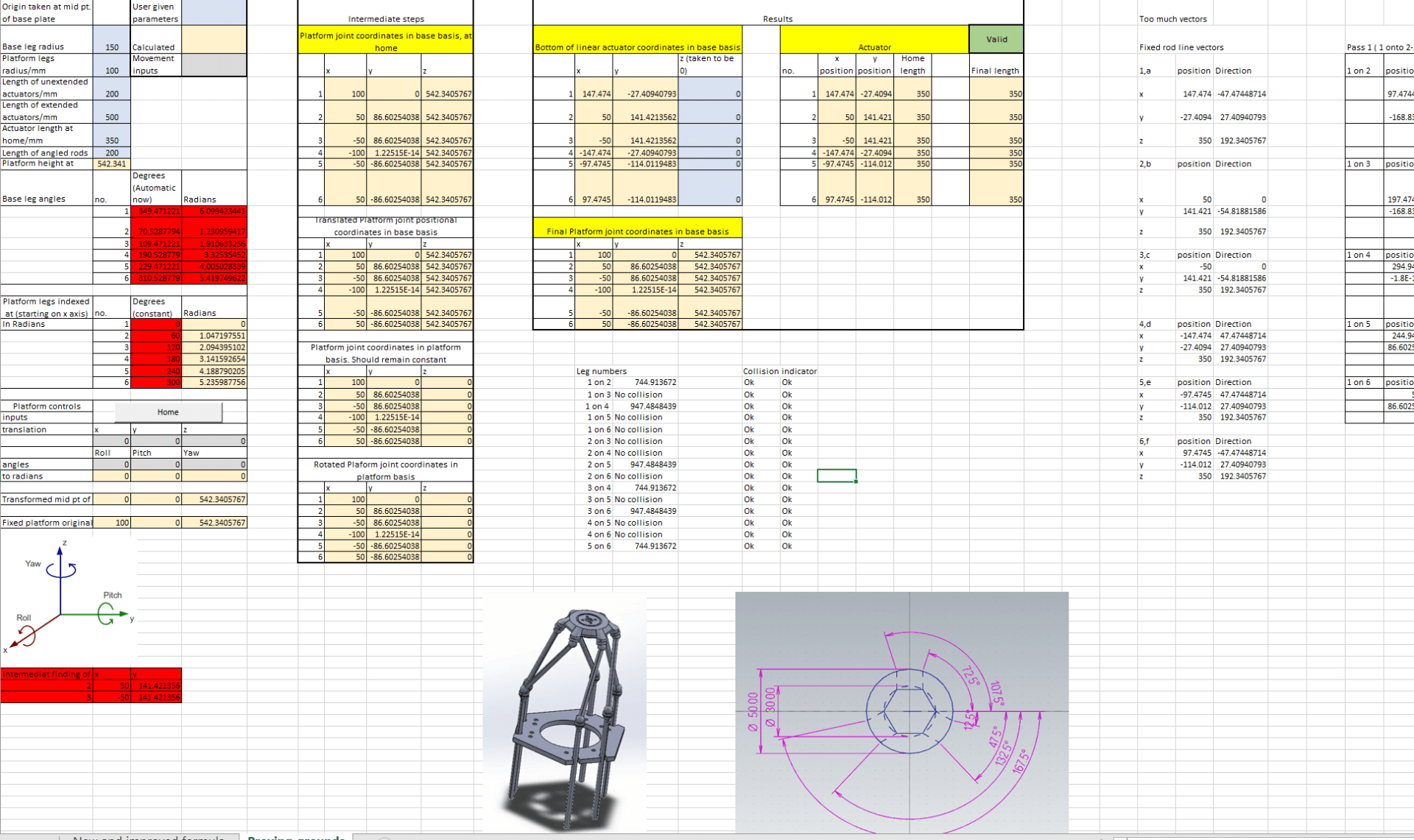
An updated and improved stable motion study that uses belt actuators has been completed by the hardware team, this will help us to model the other parts needed to optimize the movement of the platform.

A simple GUI application using typescript is currently in development, this will serve as the interface for our final platform. We intend for his application to be an all-in-one package that handles serial port connections, streaming data, our math logic, and interpreting inputs from the user.

1st prototypes of actuator platform adapter

1st prototype of actuator mounting base adapter

1st prototype of actuator  base mounting adapter with actuator attached

Hexapod GUI

Revised motion study


2nd platform prototype

Week 5 (14 June – 20 June)

Week 5 (14 June – 20 June)

The linear actuator purchased in week 3 arrived and we tested its capabilities. Unfortunately, the specifications listed on its product page do not match its actual performance. The listed speed of the actuator was 30 mm/s while the measured speed was closer to 15mm/s. Additionally, due to the lead screw design of the linear actuator, a backlash error is present which compromises the precision of the position of the platform. Due to this, we decide to choose belt-driven linear actuators instead to run our platform.

While trying to use Marlin 2.0 as the firmware for our platform, we realized that Marlin 2.0 does not natively support 6 stepper axes, this results in a lack of support for homing and other features for the unsupported axes. Hence, the coding team needed to use a prerelease version of Marlin in order to implement 6 stepper axes support. After building and uploading this version of Marlin to the Arduino, we tested the motor movements using Pronterface as a host to see if stepper motors worked properly. Unfortunately, this was not the case as the resultant movements of the stepper motors were glitchy and stable. Further optimization of the code has to be done before testing actual linear actuators. A solution to convert inputs into actuator lengths and streaming to Marlin is also needed to be coded. 

Due to the hexagonal nature of the orientation of the actuators, attaching them to the uniformly spaced breadboard requires individual custom parts for attachment. The hardware team has to design and fabricate this part while leaving very little play to ensure the precision of the platform is not compromised.

The Arduino Ramps 1.4 only natively supports 5 stepper drivers on the board, hence an expansion board has to be purchased and connected in order for all 6 stepper drivers to be run off the same Arduino.

Week 4 (7 June – 13 June)

Week 4 (7 June – 13 June)

The research team has calculated that the range of motion for 150mm base radius and 100mm platform radius is X, Y: 100mm, pitch, roll, yaw: 45 degrees. This range of motion is good to hear as it far exceeds our requirements for the applications we intend to use the platform for. Nevertheless, these values are theoretical and the actual range of motion should be considerably less especially with the load. 

The research team is also re-classified into the coding team as their focus has almost shifted entirely into creating an interface and implementing coding logic with the mathematical equations needed. 

A simple Matlab GUI was created by the coding team, linking the mathematical equations to the GUI application and implementing event listeners for all of the components are a work in progress and are expected to take a while to fully complete. This is partially due to less than ideal documentation of Matlab which slows down the development of the code considerably. This progress is in vain though as we realized that in order for our platform to work well, synchronous input will be required and Matlab does not support this feature. We decided to abandon working on Matlab and C++ and use widely available firmware such as Simtools, Mach 3, and Marlin as these software readily support synchronous input.

matlab begone

The issues discovered previously regarding rod lengths changing have been rectified. The motion study is now stable and without error.

The 1st platform plate prototype has finished 3D printing, however, due to print issues, one of the edges of the platform is deformed. This deformity does not seem to affect usability and only affects the aesthetic appearance of the platform.

The optical breadboard was quoted to be $400 from the mechanical workshop in SPMS. As the price on Aliexpress for the same dimensions is lower, we decided to purchase the optical breadboard online.

The ball joints and rods ordered a week ago have finally arrived. However, the rods received were not threaded, hence we are unable to attach the ball joints to it. We will need to 3D print custom rods to replace the defective rods received.

In regards to electronic components, we decided to use an Arduino Ramps 1.4 as the controller and TMC2209 as motor drivers.

MatLab GUI

Rod and Platform assembled together


Magnetic joint and unthreaded rod

Deformed platform


Week 3 (31 May – 6 June)

Week 3 (31 May – 6 June)

We completed our first set of purchases which include magnetic ball joints and carbon rods. 1 A2 HB60 actuator was also purchased for testing to evaluate whether its specifications can meet our requirements. If the linear actuator is suitable for our use, we intend to purchase more.

The purchases were mainly made on sites such as Aliexpress and typically shipped from China. As a result, the shipping time ranges from a week to up to a month based on the estimate by the website, actual shipping time maybe even longer. In order to ensure we get the parts we need on time and prevent delays in the progress of the project, we should plan our purchases early and prioritize vendors who offer faster shipping first over a vendor who has a slightly lower price but much slower shipping.

The unintended pitch and roll issues of the motion study were partially rectified. After reviewing the mathematics model used in the excel sheet and the model rendered, we found some discrepancies regarding the dimensions of the rods and platform radius. After making some adjustments, most of the unintentional pitch and roll are nullified. The other contributing factor to the pitch and roll issues was found out to be the rod lengths changes during calculation even though they should be fixed in value. The research team will look into this in order to fully rectify the issue.

The research team commenced on converting the mathematical equations into coding logic. Matlab was initially used but we quickly found out some major flaws with the program that could adversely affect the performance of our platform down the line. Though Matlab is great for ease of use regarding math functions and plotting graphs. Its performance pertaining to calculating many commands quickly and streaming data to a device is less than ideal and would introduce a lot of lag and processing time.

Due to the possibility of Matlab being a bottleneck to the performance of our platform, we are exploring other options to process our mathematical equations and commands while we work on Matlab. Tentatively, C++ is an option we are pursuing. The research team is also tasked with finding out the theoretical range of motion given a platform of 150mm base radius and 100mm platform radius.

Regarding the electronics we planned to use, we found out that ESP32 does not work optimally with DM542 drivers. This is because the DM542 motor driver requires 5V logic for its step and direction pins to work and the ESP32 runs on 3.3V pin logic. We will have to source for alternative parts to run our platform.

A feature of our platform that we are exploring is adding modularity to the system. This would allow the legs of the Stewart platform to be placed in non-standard formations and still function. Changing the number of legs of the platform for different applications and different DOF platforms is also possible with the modularity feature. We plan to mount the platform on an optical breadboard to enable the modularity of the platform. In order to procure this optical breadboard, we plan to approach the mechanical lab for a quote before resorting to purchasing online as fabricating it in SPMS would be faster and more customized to our requirements.

The hardware team has also started modeling the parts to be 3D printed such as the platform and rods.

Week 2 (24 May – 30 May)

Week 2 (24 May – 30 May)

Our Finance IC Keith compiled the costs of the parts we intend to purchase which amount to $1510. The cost of the project is pretty high and we are trying to source alternative parts so that we would have spare budget in order to replace damaged parts or purchase additional ones.

The research group completed an excel sheet draft and a Matlab simulation using the researched math which would take in values of x, y, z, roll, pitch, yaw, and output the actuator lengths required to achieve the pose. 

Some of the challenges faced include conflicting ideas and mathematics in different research papers. Our version of the Stewart-Platform which employs fixed actuators and freely rotating rods is also vastly different from the commonly researched and used version of Stewart-Platforms which use freely moving linear actuators or servo motors. As a result, we had to make some modifications and adapt the equations found in the research papers for our Stewart-Platform. Unfamiliarity with Matlab also made the creation of the simulation difficult.

The hardware group finished its first revision of the Stewart-Platform model and implemented the mathematics researched by the research group into the model to produce a motion study.

The motion study showed that a translation in the x and y direction would result in an unintended roll and pitch of the platform. Further investigation is needed to understand and rectify this issue.

The research team will continue to optimize its mathematics model and develop a way to determine the range of motion of the platform and possible collisions between legs given a configuration of the Stewart-Platform.

In terms of our choice of electronic components and linear actuator, we decided to use the ESP32 as the microcontroller, DM542 as the motor driver, and the A2 HB60 as the linear actuator.

Preparation for the 1st presentation on the 28th of May also has to be completed.


Unintended roll and pitch during translation as shown in the motion study

28 May 1st Presentation

A small snapshot of calculations excel sheet


Skip to toolbar