We completed our first set of purchases which include magnetic ball joints and carbon rods. 1 A2 HB60 actuator was also purchased for testing to evaluate whether its specifications can meet our requirements. If the linear actuator is suitable for our use, we intend to purchase more.
The purchases were mainly made on sites such as Aliexpress and typically shipped from China. As a result, the shipping time ranges from a week to up to a month based on the estimate by the website, actual shipping time maybe even longer. In order to ensure we get the parts we need on time and prevent delays in the progress of the project, we should plan our purchases early and prioritize vendors who offer faster shipping first over a vendor who has a slightly lower price but much slower shipping.
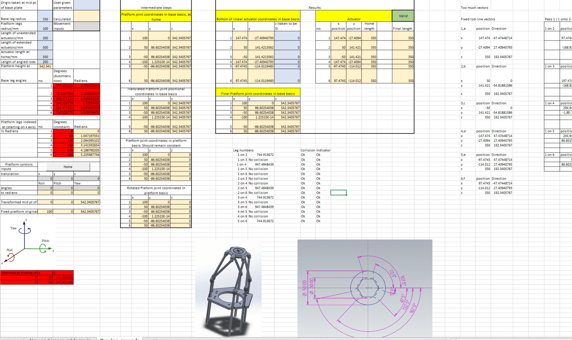
The unintended pitch and roll issues of the motion study were partially rectified. After reviewing the mathematics model used in the excel sheet and the model rendered, we found some discrepancies regarding the dimensions of the rods and platform radius. After making some adjustments, most of the unintentional pitch and roll are nullified. The other contributing factor to the pitch and roll issues was found out to be the rod lengths changes during calculation even though they should be fixed in value. The research team will look into this in order to fully rectify the issue.
The research team commenced on converting the mathematical equations into coding logic. Matlab was initially used but we quickly found out some major flaws with the program that could adversely affect the performance of our platform down the line. Though Matlab is great for ease of use regarding math functions and plotting graphs. Its performance pertaining to calculating many commands quickly and streaming data to a device is less than ideal and would introduce a lot of lag and processing time.
Due to the possibility of Matlab being a bottleneck to the performance of our platform, we are exploring other options to process our mathematical equations and commands while we work on Matlab. Tentatively, C++ is an option we are pursuing. The research team is also tasked with finding out the theoretical range of motion given a platform of 150mm base radius and 100mm platform radius.
Regarding the electronics we planned to use, we found out that ESP32 does not work optimally with DM542 drivers. This is because the DM542 motor driver requires 5V logic for its step and direction pins to work and the ESP32 runs on 3.3V pin logic. We will have to source for alternative parts to run our platform.
A feature of our platform that we are exploring is adding modularity to the system. This would allow the legs of the Stewart platform to be placed in non-standard formations and still function. Changing the number of legs of the platform for different applications and different DOF platforms is also possible with the modularity feature. We plan to mount the platform on an optical breadboard to enable the modularity of the platform. In order to procure this optical breadboard, we plan to approach the mechanical lab for a quote before resorting to purchasing online as fabricating it in SPMS would be faster and more customized to our requirements.
The hardware team has also started modeling the parts to be 3D printed such as the platform and rods.
We completed our first set of purchases which include magnetic ball joints and carbon rods. 1 A2 HB60 actuator was also purchased for testing to evaluate whether its specifications can meet our requirements. If the linear actuator is suitable for our use, we intend to purchase more.
The purchases were mainly made on sites such as Aliexpress and typically shipped from China. As a result, the shipping time ranges from a week to up to a month based on the estimate by the website, actual shipping time maybe even longer. In order to ensure we get the parts we need on time and prevent delays in the progress of the project, we should plan our purchases early and prioritize vendors who offer faster shipping first over a vendor who has a slightly lower price but much slower shipping.
The unintended pitch and roll issues of the motion study were partially rectified. After reviewing the mathematics model used in the excel sheet and the model rendered, we found some discrepancies regarding the dimensions of the rods and platform radius. After making some adjustments, most of the unintentional pitch and roll are nullified. The other contributing factor to the pitch and roll issues was found out to be the rod lengths changes during calculation even though they should be fixed in value. The research team will look into this in order to fully rectify the issue.
The research team commenced on converting the mathematical equations into coding logic. Matlab was initially used but we quickly found out some major flaws with the program that could adversely affect the performance of our platform down the line. Though Matlab is great for ease of use regarding math functions and plotting graphs. Its performance pertaining to calculating many commands quickly and streaming data to a device is less than ideal and would introduce a lot of lag and processing time.
Due to the possibility of Matlab being a bottleneck to the performance of our platform, we are exploring other options to process our mathematical equations and commands while we work on Matlab. Tentatively, C++ is an option we are pursuing. The research team is also tasked with finding out the theoretical range of motion given a platform of 150mm base radius and 100mm platform radius.
Regarding the electronics we planned to use, we found out that ESP32 does not work optimally with DM542 drivers. This is because the DM542 motor driver requires 5V logic for its step and direction pins to work and the ESP32 runs on 3.3V pin logic. We will have to source for alternative parts to run our platform.
A feature of our platform that we are exploring is adding modularity to the system. This would allow the legs of the Stewart platform to be placed in non-standard formations and still function. Changing the number of legs of the platform for different applications and different DOF platforms is also possible with the modularity feature. We plan to mount the platform on an optical breadboard to enable the modularity of the platform. In order to procure this optical breadboard, we plan to approach the mechanical lab for a quote before resorting to purchasing online as fabricating it in SPMS would be faster and more customized to our requirements.
The hardware team has also started modeling the parts to be 3D printed such as the platform and rods.