Contents
Overview
Two types of infrared sensors, the GP2Y0A21YK short range sensor (10 – 80 cm) and the GP2Y0A0AYK long range sensor (20 – 150 cm), were used to detect obstacles in the arena. Infrared sensors were used as opposed to ultrasonic sensors for their simplicity as ultrasonic sensors tend to produce ghost echoes. Furthermore, we selected a mixture of 5 short range and 1 long range sensors which were positioned in the diagram shown below. The 2 short range sensors on the right were used in our right wall hugging algorithm, while the long range sensor on the left was used to detect obstacles to the left of our robot. The 3 short range sensors at the front were used to detect obstacles in front of the robot.
Infrared Sensors
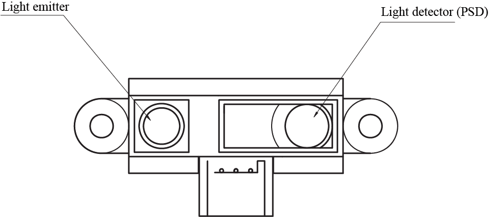
Each IR sensor consists of a light emitter and a light detector. To measure the distance between an object and the sensor, the light emitter emits a beam of infrared light. This beam reflects off an object before reaching the light detector, where an ‘optical spot’ is formed. The signal processing circuit in the sensor then uses the position of the ‘optical spot’ to estimate the distance from the reflective object. As seen in the diagram below, an object at point A, which is further away, will give a different ‘optical spot’ from an object at point B, which is nearer.
The sensor then outputs an analog signal which may be read by the analog pins on the Arduino via the analogRead() function.
Sensor Performance
The data sheets of the sensors describe the relationship between the distance from sensor to reflective object and the output voltage. From the 2 graphs below, the working range of the sensors are 10 – 80 cm and 20 – 150 cm respectively, as a voltage of 2V might mean that the object is either 10 cm or 30 cm away from the long range sensor. To eliminate ambiguity, the range of the sensor is thus defined as such.
Further experimentation with our sensors led us to reduce the working range of the short range sensor to 10 – 20 cm (so that it can detect obstacles 1 – 2 blocks away), and the long range sensor to 20 – 70 cm (so that it can detect obstacles 2 – 7 blocks away) as these values gave us the most accurate readings. This can be seen in the above image on the right.
The graphs also demonstrates how the sensor response is non-linear, meaning that a small change in output voltage does not necessarily translate to a small change in distance. To simplify the conversion of output voltage to distance, the SharpIR library was used. We modified the equations in the library to suit our sensors, resulting in the following equations for the short range and long range sensors respectively. The output voltage from the sensor was mapped to a range from 0 to 5000 and saved into the variable voltFromRaw.
Short range: distance = 27.728 * pow(voltFromRaw / 1000., -1.2045)
Long range: distance = 61.573 * pow(voltFromRaw / 1000., -1.1068)
Other Sensor Considerations
As the sensor’s return voltage is relatively unstable, we sought to take the median of 25 values to improve the sensor’s accuracy. This number was selected considering the time it took to obtain the sensor readings, and the degree of accuracy it offered. With these in mind, we were able to achieve stable performance with our sensors.


