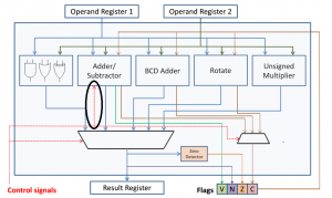
If you refer to “Computer Arithmetic Part 2” slides 9, 10 and 11, you will see Add’.
This decides the masking of operand register 2, and either creates ADD or SUB operation. Look at the Adder/Subtractor block again, and see the number of inputs. Reconcile with the mentioned slides. You should now understand why there is a control signal to the add/sub block.
—
Dear sir,
I attach an edited picture of the diagram.
Is the circled part the “control bit” of each functional block (add/subtract, logical operation, etc.)? If it is, then there should be some branches from the control to other functional blocks (other than the add/sub block)?
I did not see that there is a branch from the control signals to the add/sub block. I was referring to my black and white printed lecture notes. It is not too obvious when I took a look at my printed notes.
Thank you.
Regards,
Edwin Candinegara
