From the previous section, you would have read about our attempts at allowing the vehicle to reach a high-enough speed after overcoming magnetic drag. As we were testing if those setups would work, we simultaneously designed our vehicle according to the needs.
In the first step, we planned for the vehicle to be moving over a linear track. Due to the high speed movement through air, the vehicle was required to have an aerodynamic structure. In the subsequent phases of our project, however, we shifted the direction of our project such that the vehicle mass could be minimised. This led to a change in design of the vehicle as well.
Prototype I: Aerodynamic Structure
In the initial stages, the plan was to create a downscaled prototype of the existing Hyperloop pods and their test track. The existing test track built by SpaceX is between 1.25 and 1.51 km, and is meant to be a low-pressure tube with an aluminium sub-track.
Hence, we decided to downscale and simplify our setup to be just a conducting track (aluminium or copper), but in open air instead of a low-pressure tube. Our vehicle was to be moved at high speeds along the linear track.
At this stage, our track was planned to be a long, linear copper track (of at least 15 m) to allow the speed of the vehicle to build up to something fast enough for levitation to occur.
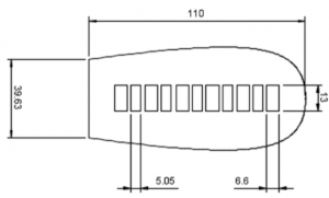
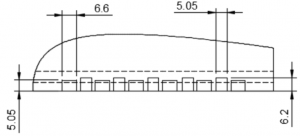
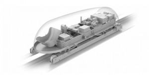
Since our vehicle was going to be moving at high speeds through air, it would have to take on an efficient aerodynamic external structure, which we chose to adapt from the MIT Hyperloop Project. Our magnet array was to be placed at the bottom of the vehicle as close to the track as possible.


To build the first prototype, we 3D-printed our vehicle in two parts:
- A bottom plate containing the slots in which the magnets will be placed — the slots were customised to the dimensions of the N42 neodynium magnets that we would be using; and
- A top shell adapting the aerodynamic shape with downscaled specifications used in the MIT project.
Change in Track Design
As the project progressed, we realised that having the vehicle travel linearly at high speed and have sufficient time to observe its levitation over the track would be extremely difficult. (For more on this, please read Option III in this page.)
First, the track would have to be sufficiently long to allow the vehicle’s speed to be built up, followed by some lag time to allow for the observation of the vehicle’s levitation. Acquiring a long conducting track (e.g. copper) would be very costly to acquire and transport for a proof-of-concept project.
At the same time, as the vehicle is moving at a high speed in a linear fashion, banking of the track would be needed. This is to ensure that the vehicle stays on the track and remains stable in its movements. However, if the vehicle were to move from side to side due to the banks, its stability would still not be guaranteed. The added friction from grazing along the banks might also limit its buildup of speed.
Secondly, as the vehicle would be moving at extremely high speeds, levitation would be difficult to observe with the naked eye — something like a high-speed camera will be needed.
To resolve this problem, we decided to build a circular track instead so that the vehicle can build its speed up in a circular manner instead of linearly. This would allow buildup of speed in a limited space.

The initial setup to be built is shown in this image. The vehicle would be affixed to a sliding mechanism to allow for its up/downward movement (to visualise levitation), with a counterweight balancing it out. The vehicle was then to be rotated by the motor (attached to the same main vertical rod as the vehicle) over a circular copper sheet.
The speed of the vehicle builds up in a circular manner fast enough so that levitation would occur. The levitation can then be observed by looking at the vertical displacement along the sliding mechanism.
Yet, we again realised that while this setup resolves a lot of the problems we faced previously, it would still be hard to observe the vertical displacement of the vehicle as it would be travelling at very high speeds.
Therefore, our final setup (detailed in Design section) was to change the design of the setup in the image above such that the copper sheet would be spun at high speeds relative to the vehicle instead. In other words, the vehicle would be held at a stationary position above the track, but the track would be moving at higher and higher speeds under and relative to it.
Since the vehicle would be stationary (in terms of horizontal displacement), it would be easy to observe its vertical displacement caused by levitation.
Prototype II: Prioritise minimal weight

In this new setup, air resistance on the vehicle would be less of a priority since the vehicle is no longer moving at high speeds through air. Therefore, we would not have to use an aerodynamic design for the vehicle and the mass of the vehicle could be largely reduced to increase ease of levitation. The vehicle design was thus simplified further (since aerodynamics were no longer a concern), to only be a plate containing the same magnet slot design as seen in Prototype I.
As we were building the prototype, however, we made more changes to the system design to tackle other subsequent challenges.
Finally, we arrived at our final design, which can be found in the section on Design.
Credits
- https://cdn.atraining.ru/docs/TubeSpecs.pdf
- http://web.mit.edu/mopg/www/papers/MITHyperloop_FinalReport_2017_public.pdf

