
When: 26 June 2019, 10am
Members present: All
Assembling the LA Module ✌
LA Mount Mk III
We collected our LA Mount Mk III, which finally printed out perfectly! After that, we secured the motor and piston structure to the LA mount. We faced a bit of difficulty putting in the screws due to the super exact fit, but in the end we managed to get it done. Our LA module is now ready to be mounted onto the aluminium frame!

Linear Actuator Mount Mk III, with the stepper motor and linear actuator secured into place.
Assembling the Aluminium Frame
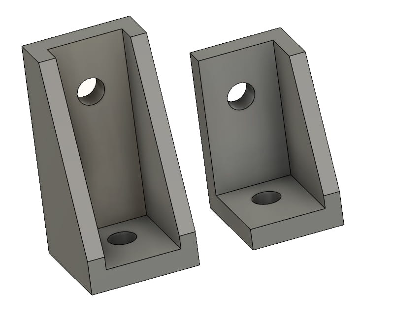
Major Brackets Mk III
Since we printed our connector brackets for the aluminium frame overnight, we could work on our aluminium frame today. The two connector brackets (Major Brackets Mk III) were printed and used to connect the aluminium profile pieces at right angles using M5 screws and T-slot nuts. Thankfully, no, we did not have to drill any of the profiles. (We don’t have any pictures of the bare aluminium frame, but you can see how it looks like under the “Attaching the LA Module” section later!)
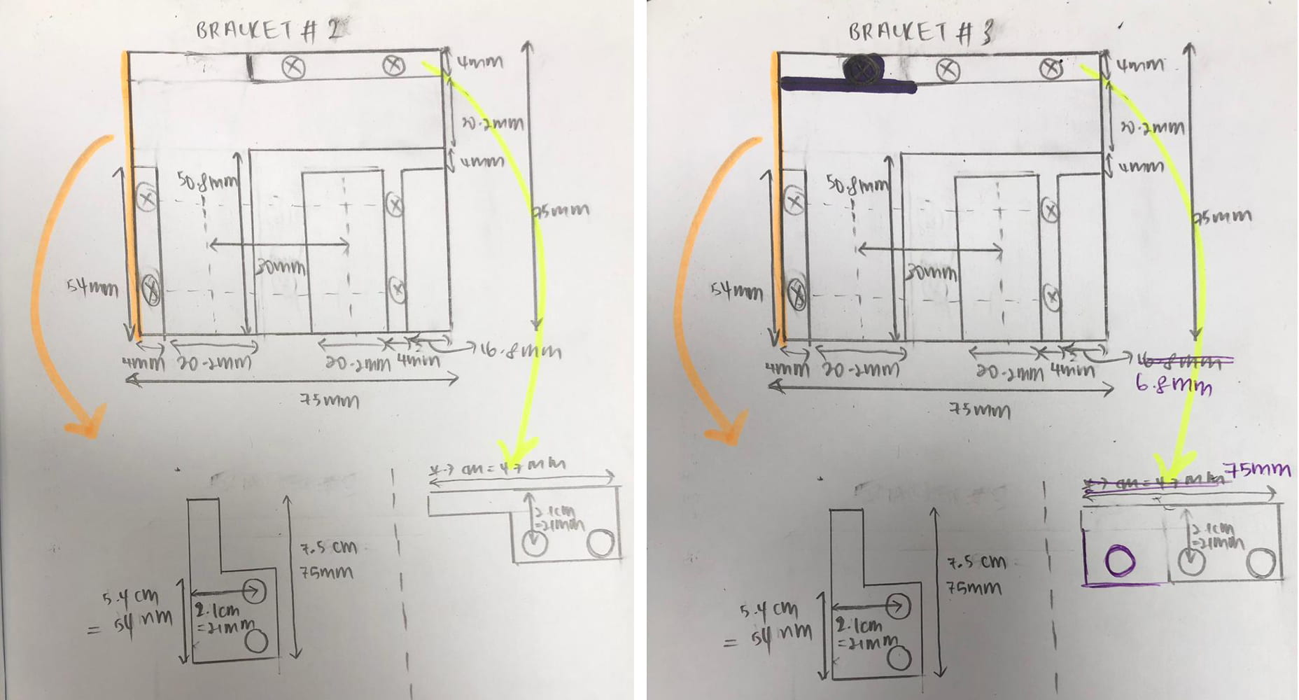
Here are Vanessa’s notes on the changes we made from Major Bracket Mk II to Mk III.
Minor Brackets Mk I
Once the aluminium profiles were connected, we tried to secure the bottom section to the 3D printer and a horizontal support (another aluminium profile) with corner brackets. The first corner brackets (see below) we printed were of a design we found on Thingiverse 🤫. However, the holes of these corner brackets were slightly too small for our screws, and the corner bracket itself was very small, making it difficult to screw in both screws at the same time. They were near-impossible to use.

Minor Bracket Mk I. We printed 6 of these from thingiverse.
Minor Brackets Mk II
Following this, we decided to make our own brackets to fit our specific needs. We modeled two differently- and specifically-sized brackets in Fusion360. Although their primary function is to secure two perpendicular aluminium profiles together, their different non-standard heights also allow them to fulfill a secondary function: to aid in supporting the weight of the linear actuator module.
The Fusion360 models of our new Minor Brackets Mk II. There are technically 2 different models shown here, a 4-faced taller (4 cm) and a 3-faced shorter (3 cm) piece.
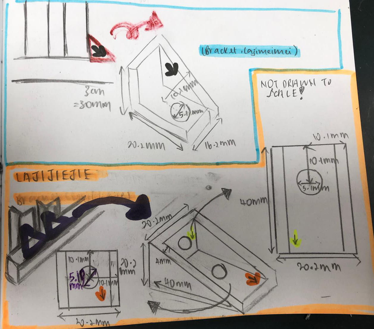
Vanessa’s notes on the dimensions needed for the small bracket pieces.
Right before we left for the day, only the smaller piece on the right managed to finish printing. We removed it and sent another job for printing overnight. We didn’t test it just yet, but here’s its preview!

Minor Bracket Mk II (3-faced).
Attaching the LA Module to the Frame
After building the aluminium frame, we mounted the LA module onto the aluminium frame using the same M5 screws and T-slot nuts that we used to build the aluminium frame. Because the LA module is elevated above the table level, we placed a box below the module as a temporary support.

The aluminium profile and linear actuator are now secured to the 3D printer, with the help of our Major Brackets Mk III and LA Mount Mk III.
Testing the LA module
Based on our manual “driving” of the motor, the linear actuator module is supposed to work (mostly) smoothly with the LA mount. However, when we tried to run the code to run the motor, all we got out of it was an ugly screeching sound ⚡⚡. Tony suggested that the issue lies either in our wiring or in our code. With Tony’s help, we found out that the issue was that the microstep pin was disconnected. After fixing that issue, the motor ran smoothly!! The movement of the piston structure in the linear actuator was not as smooth, but it’s a start!
Video of the LA working fine in its ‘upside-down’ position, attached to the LA Mount that is in turn attached to the aluminium profile, that is in turn attached to the 3D Printer.
Tubing Troubles
Securing the Outer Tube
Profile-Tubing Connector Mk I
We figured out a way to secure to outer tube to our aluminium profile by using a 3D printed bracket, which would be mounted onto the aluminium profile. The metal piece used to secure the outer tube will be put through the 3D printed overhang, then clamped down with 2 nuts. We quickly designed and sent the model for printing.

Profile-Tubing Connector Mk I.
Video of how the Profile-Tubing Connector Mk I helps to keep the outer tubing in place. Listen out for Gabriel’s “Smelly” at the 5 second mark of the video.
It printed out perfectly! It was able to fit easily onto our aluminium profile too, but with one issue…

The Profile-Tubing Connector, as mounted onto our added aluminium frame.
… The overhang was in the wrong position. 😔 This may cause damage to the tubing over short-term sustained use, or even jam the piston as it would constantly encounter an ‘obstruction’ due to the bent tubing. To fix this misalignment, we redesigned the connector bracket connecting the aluminium profiles to make its horizontal width shorter and to increase the support between the aluminium profiles. It took a while to print, but Vanessa happened to stay late in the M&T Lab today, so she fixed it up for us.

Major Bracket Mk IV in place with the Profile-Tubing Connector Mk I.
Major Bracket Mk IV now allows for the Profile-Tubing Connector Mk I to be nearer to the edge of the left edge of the aluminium profile, aligning it better with the piston head of our stationary linear actuator.
Revised Main Body Front Cover
However, we kind of forgot that we also need to clamp the outer tube to a place near to the Main Body in order to secure the outer tubing at two points (which we found was necessary as detailed in post [#11]). We’re gonna have to modify our Main Body again to accommodate the clamp for the outer tube. Alexis helped us to come up with this design below to house and clamp the metal piece which secures the outer tube. With this design, we only need to reprint one half of the Main Body, which will save us some time. 😚

Main Body Mk III for the front cover, as sketched by Alexis. Notice Claudia’s “Nestea” contribution at the top margin.
The idea behind the design is to just add a structure above the tubing opening of the main body (The actual main body design is left untouched). This horizontal structure can be ‘clamped’ by the two nuts of the adaptor piece, in a similar manner to how the Profile-Tubing Connector piece is secured. Even though there’s a seemingly precarious overhanging portion, if all is printed well, it will be supported by the other half of the main body. It’s also designed as an ‘open box’ both for stability and for us to be able to screw the lower nut in place.

Main Body Mk III design, with the main change being the addition of the ‘umbrella’ at the top.
Of course, this piece will take a while to print so we left it overnight 🌙. It shouldn’t have much issue since it was printed with the orientation seen above, so supports for the overhang are unnecessary.
Securing the Inner Tube
Some ideas that we came up with on how to secure the inner tube to the piston structure:
- Cable Tie (temporary solution)
- Clamp (similar to designs used for Needle-Tubing Connector and Main Body)
We decided to jump straight into it and came up with a design for Option 2.
Linear Actuator-Tubing Connector Mk I
[INSERT SKETCH OF LA-TUBING CONNECTOR DESIGN]
Alexis’ sketch for the concept of the LA-Tubing Connector.
Similar to the clamping mechanism used for the Needle-Tubing Connector, the design involves two pieces that must be screwed together to secure the inner tubing between them. Additionally, a lower hollow area was made to accommodate for the size of the head of the piston structure, which would be clamped along with the inner tubing using a bigger screw that fits through the (already existing) hole at the head of the piston structure.
Vanessa picked up the piece from the printer right before she left, so we’ll be testing it out tomorrow. Til then! 🌠

The two inner halves of the LA-tubing Mk I.