Initial Phase
Initially our idea was to create a pair of roller skates that can retract its base with wheels into a platform, so that the user is walking on flat surface.


After obtaining our roller blades, we also discussed simply adding brakes or locks to lock the wheels so that the wheels will not move as the user walks uphill or on stairs. We decided to add a “hook” which enters through the gaps on the frame of the roller blade to lock the wheels, similar to the concept of a doorstop.


However, we realised that this idea may not be optimal as the commercially available inline skate frames are not meant for retraction or wheel locking, hence we decided to change the direction of our project to make our own electric roller skates using aluminium profiles and skateboard wheels, and further add the wheel-locking/retraction mechanism. We planned to use the skateboard truck to mount our wheels and create our own truck for the electric wheel to make it a 3-wheel drive roller skate.
After some exploration, we decided to focus on wheel locking mechanisms which still serve our original purpose. The development of retractable structure was on hold. 4 wheel locking mechanisms were brainstormed and tested.
- wheel clamp
- corkscrew brake
- wheel chock
- gear lock
Wheel clamp:
A toggle clamp is mounted on to the frame to brake the wheels. Motors are used to lock and unlock the clamp.

Corkscrew brake:
A corkscrew brake is mounted on top of the wheels, which can screw a rubber part downward to lock the wheels.

Wheel chock:

A motor between two wheels can push the chock on two sides towards and away from wheels to lock and unlock.
Gear lock:

A gear is attached to the wheel and a screw is lowered into the teeth of the gear via a toggle clamp to stop the wheel from rotating.
Prototyping Phase
Prototype 1: Electric skates + wheel clamp

In our first prototype, the white wheels are normal longboard wheels with 59 mm diameter and 45 mm thickness purchased from Decathlon, while the orange wheels and the black truck were purchased from Ether Skateboards with one of the orange wheels being motorised. The orange wheels are 72 mm in diameter and 51 mm in thickness, and has an operating voltage of 25.2 V and a power of 400 W. The motor is powered by a 25.2 V battery with an output of 5.2 Ah and is controlled via hall sensors. The circuit board and battery is shown below:

For the remote control, it has several functions. As the user pushes the control forward, it accelerates the motor while when the control is pulled backwards, it stops the motor. The reverse button allows the motor to change its direction of rotation to either move backwards or forward. The wireless sign indicates whether the circuit board is turned on, and the percentage indicates the amount of energy left in the battery. The remote control itself is charged via micro-USB. It also has the ability to change the speed of the motor.
By clamping the wheel with the toggle clamp, it exerts enough friction and slightly displaces the wheel to stop it from rotating.


Pros:
- Effective wheel-locking. Wheel was unable to rotate even with large amounts of rotational force applied.
- Simple mechanical design.
Cons:
- Difficult to motorise. A lot of force is required to lock/unlock the clamp and MG995 servo motor is unable to deliver that amount of force.
- Difficult to mechanically lock/unlock all clamps at once.
- Clamp may deform wheel due to pressure on the wheel.
Prototype 2: Motorised wheel clamp (with MG995 servo motor)
As we didn’t want to modify the inner components of our MG995 motors to rotate 360° and risk damaging the motors, we used a toggle clamp to lower a wheel clamp onto the wheels, in a manner similar to the corkscrew brake.
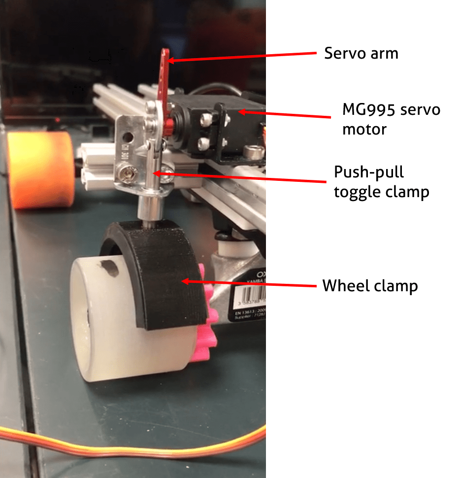
In order to motorise the clamp, we modified the toggle clamp by filing away the rivet and attaching the clamp onto the servo arm, so that the handle is controlled by the servo arm. Meanwhile, we used an Arduino and a potentiometer to control the movement of the motor and servo arm. The circuitry is shown below:

We realised that the voltage provided by the battery pack far exceeds the operating voltage of the Arduino and the motor which is 5 V, and it would be a hassle to use a separate power supply for the Arduino. Hence, we used a variable voltage regulator which is connected to the circuit board for the wheels to reduce the voltage provided to the Arduino and motor. As such, by turning the potentiometer, the servo arm is able to rotate downwards which allows the wheel clamp to be lowered onto the wheels.


We also tested the clamp when the wheels were activated. After turning the potentiometer to lower the wheel clamp, it effectively locks the wheels and prevents it from rotating, causing the skate to “drift”. Note that the final product will not be using the potentiometer to control the clamp as this is only a prototype and for demonstration purposes, the final product will be controlled via Bluetooth from a smartphone.
Pros:
- Easy to motorise.
- Provides sufficient force to stop wheels from rotating.
Cons:
- With wear and tear, the surface of the wheels might become smooth and the clamp might not be able to provide sufficient frictional force.
- Bulky design because of extensions on the sides.
Prototype 3: Motorised gear lock
Similar to the motorised wheel clamp, the gear lock uses a toggle clamp controlled by a servo motor to release a screw into the gaps of the gear teeth attached to the wheels. The gear is 3D-printed and is screwed into the wheel by drilling holes in the rubber of the wheel beforehand. Similar to the wheel clamp, the motor is also controlled via Arduino and potentiometer. The mechanism is shown below:

From several tests, the rubber fitting was fragile and broke off, so we decided to simply use a screw for the lock.


Pros:
- Effective locking.
- Even if the gear lock does not land directly in the gap of the gear teeth, we have designed the gear such that the teeth is sharp hence the lock would slide down the sides of the teeth and land in the gap.
- Compact design. The motor and gear can be designed to be kept underneath the frame.
Cons:
- As we’re using screws for the lock, it may cause wear and tear into the plastic gear and cause the lock to be ineffective.
- Small probability that the lock lands directly on the teeth and is unable to slide into the gap even after rotating.
Prototype 4: Wheel chock

We took the plastic shoe frame that came with the inline skates bought from Decathlon and attached to a makeshift inline skate frame made from aluminium profile, and 83mm longboard wheels were attached to the aluminium frame. A motor housing and wheel chocks with corkscrew mechanism was intended to be added and the frame was intended to be from 3D-printing, however the dimensions were slightly off and the printed frame could not be used. There was also time constraint on designing new motor housings and wheel chocks, so this is an unfinished prototype.
Final Product

Our final product consists of 3 main parts: the aluminum profile body with 3D printed back support secured onto the structure; wheel clamps connected to servo motors, same as prototype 2; circuits board connecting and powering everything.
The wheel clamp design was kept from prototype 2 as the best wheel-locking mechanism for us. It is replicated onto all wheels. The body was assembled with 2020 aluminum profile and back bracing to support ankle and calves. Velcro straps were used to secure foot onto the skates. Extensions were also connected to the aluminum profiles to mount toggle clamps and maximize foot space.

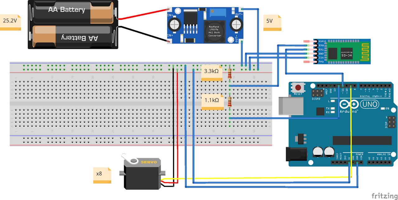
The figure above shows the connection between the different parts and the circuiting. The battery provides 25.2V of voltage. The electric wheels receive the 25.2V from the big green circuit board. The green circuit board is then connected to a LM2596 buck converter that step down the voltage to 5V.
For the app, we used the RoboRemo mobile app which can be easily configured to send signals via bluetooth to Arduino. The app is shown below. We configured the “lock” button to send a “1” signal to the bluetooth while the “unlock” button sends a “2” signal to the bluetooth, which can be explained further in the Arduino code.

The Arduino code is shown below:


In summary, when the “lock” signal is sent from the phone (indicated by 1), this would cause the motors to rotate clockwise for 90° into lock position. Conversely, when the “unlock” signal is sent from the phone (indicated by 2), the motors would rotate anti-clockwise for 90° into the unlocked position. This is done one motor at a time to prevent current draw from spiking and damaging our buck converter.
Final testing video showcasing both the electric skates and clamping mechanism: