Camera Mount
Pilot Design
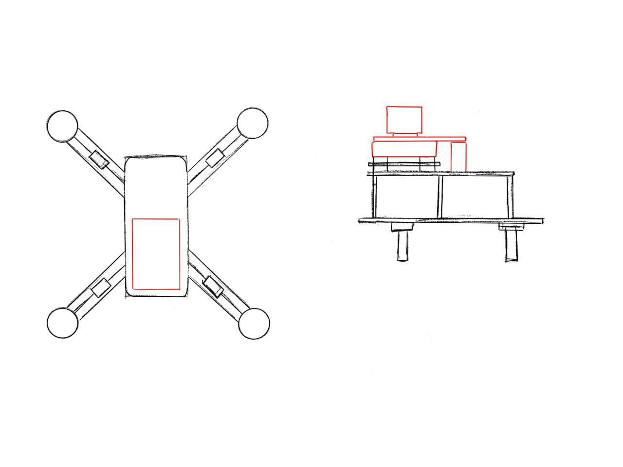
Right at the start, the plan was to include a camera mount sitting atop the drone. The mount has capabilities as in our project, to rotate to have a clear view of all angles above the drone controlled remotely.
This was our initial sketch and design for the drone, with the placement of the gimbal (in red) sitting atop the drone.

The design and fine tuning of the gimbal design was a long and arduous process. The primary idea was conceived and designed by Jianjun after seeking inspirations from the great wide web.
Designing and Printing
3D printed mounts were designed on Autodesk’s Fusion 360, which proved to be challenging for new users. However, nothing fazes JJ as he designed the entire of design in one night. The subsequent assembly, optimisation and design were done by Amanda and Grace. The following summarises succinctly the different phases of our designs along the way of improvisation.
There were 3 requirements to this gimbal:
- Lightweight (minimise weight on drone)
- Sturdy (minimise number of times the gimbal needs to be replaced after crashes)
- Versatile (to accommodate different cameras and drones)

Here is the final design of our gimbal sitting atop our F450 drone frame. We have simplified the gimbal with the servo motors being attached directly onto the 3D printed mounts as the pulley system does not give us precise motion of the camera. The camera is mounted onto one of the servo motors and there are 2 gimbals with cameras; one above and the other below the drone.
Here is a video of our final gimbal, with live camera footage from our Caddx Firefly camera transmitted at 5.8GHz to our Quanum Receiver.
Communication: RF24 Arduino Compatible Module, Joysticks
This video demonstrates the servo movement controlled with a joystick. This is done by using the 2 nRF24L01, a wireless transceiver module that transmits at 2.4GHz. This is achieved by connecting each nRF24L01 module to an Arduino with codes for Receiving and Transmitting uploaded.
We have performed various tests of the nRF24L01 module and its transmission capabilities. Stunningly, it was able to control from the gimbal camera at a distance of about 25 meters with obstacles and 2 walls in between. This is a remarkable achievement considering how even some Wifi routers at home are incapable of performing as well!
Here is a video demonstration of the gimbals moving the cameras in different angles (top and bottom). Our gimbals work to provide a 360 degree view of the drone’s surroundings and our cameras are able to record and send live video footage to our screens. The servo motors (receiver) are being controlled by the joystick (transmitter) and the motors and the joystick are being programmed using the following Arduino codes:
Receiver (Servo Motors)
Transmitter (Joystick)
This is a picture of our final controller set up. It features an Arduino Uno and a battery that is being used to power it. The nRF24L01 module can be seen at the far left. The black joysticks have been replaced by this version of the joysticks (pink) which is springless and therefore allows us better control of the servo motors (without having to constantly push on them).
Here we have a video showing the components of our controller set-up and the servo motors.
Camera
We tested our camera’s transmission capabilities using the Quanum Auto Scan 5.8GHz FPV Receiver and the VM275T 5.8GHz Micro FPV Camera. The VM275T has a 120° field of view. The footage had a lot of static, which we are trying to resolve. However, it at least shows that the camera and receiver works.
We have since switched our camera for the Caddx Firefly, which is also a 5.8GHz Micro FPV Camera. The receiver is still the Quanum Auto Scan 5.8GHz FPV Receiver. The camera has a 2.1mm lens with a 160° field of view. The video of the camera footage can be found above.


