Death of a Good LiPo

It’s a sad day today.

We went flying, as usual, at our usual spot. However, I made a fatal mistake regarding where I positioned myself.

Although we were told by Kanesh to not allow the plane to fly behind us, the reality is that weather conditions and pilot competence is not perfect.

As I was flying several rounds around the field, the wind picked up, causing the plane to fly directly over my head. Because I was standing right beside the road lined with trees, this meant that my view of the plane ended up being blocked by the foilage.

Because the Skysurfer had a tendency to roll to the left, I would normally hold the aileron stick to the right to correct this. With the plane being out of direct line of sight (and also because the white plane was flying against white sky), I lost orientation and let go of the stick, causing the Skysurfer to roll over and enter a nosedive at nearly full throttle.

The good news was that the plane missed the trees and flew between openings in the canopy, so that spared us the effort of rushing to get bamboo poles to try to recover the plane.

The bad news was that the plane crashed nose first into Old Holland Road, a proper paved driveway made of rock solid asphalt. This caused the foam at the nose area to disintegrate, crushing the battery inside. It also destroyed the FPV camera (cracked and dislodged the lens from the PCB)

It is truly sad that because of my incompetence, a brand new battery (that is famous in the drone racing scene)was destroyed. On the bright side, no servos were damaged. All the nose needed was a bit more fibre tape and it was back in action with a new battery.

Skysurfer Returns

Over the past few day as I did my revision during recess week, I could not help but think about the plane’s inability to fly on monday. Sure, it was beaten up and the aircraft’s nose has already been compressed inwards, but this could not have contributed to it not being able to fly afterwards. After all, past experience with the plane taught me that all it takes is balancing of the CG before the plane is airworthy again.

To verify that what caused the plane to crash was actually the CG, I went out to old holland road again this morning(1st October 2020). The wind at the time of my arrival was calm, perfect for flying. However, rain was imminent in the distance (buildings started disappearing) and that caused the wind to pick up speed again. I had to act fast and got to work as soon as I could.

The first few flights involved throwing the plane without throttle to see if will glide. Once I was satisfied, real tests began.

The first powered flight was rather shaky. Using a lighter 1500mAh battery meant that the aircraft was tail heavy and I had quite a challenge controlling the plane. Note how in the onboard camera footage, the plane had a tendency to pitch up, and a hard landing caused the camera to be ejected from the canopy (no damage though):

However, it wasn’t long before the 1500mAh battery was expended (somehow, running the motor also caused quite a bit of voltage sag), leaving me with only the heavier 2200mah battery to fly with. That being said, it balanced out the CG perfectly!

I intended to stay for a while longer since the first storm in front of me had blown away (and MSS’s lightning website did not report any lightning activity) but a bigger storm behind me was brewing and I started hearing thunder in the distance (upon checking the MSS website,  massive lightning activity was reported around the Tuas area), so I had to pack up and call it a day.

Pixhawk Riding on Skysurfer

Due to space constraint in the fuselage of the sky surfer, we are left with no choice but to mount the pixhawk onto the canopy of the sky surfer.

Pixhawk Mount 1.0

Initially we attempt to mount the pixhawk on to the existing foam canopy provided

Pixhawk on Foam Canopy

However, there are more electronic component that have to be attached onto plane along with the pixhawk, for e.g, safety switch, buzzer, GPS module, telemetry etc.

Therefore, there is a need for us to redesign the canopy to accommodate these various electronics.

Pixhawk Mount 2.0

We did not have the CAD model of the canopy of the sky surfer, hence we have to manually measure the current canopy and model it out on Autodesk Inventor. This new design consist of a platform to mount the GPS module, a hole for the safety switch, Micro Usb connection and a cut out to allow auxiliary connectors to be connected.

Pixhawk Mount 1.0

Subsequently, we realised that having the pixhawk expose during flight, the air pressure in the cavity maybe affect the barometer reading in the pixhawk, hence we have to find a solution to cover up the canopy.

Pixhawk Mount 3.0

In this new design, we offset backing by another 10 degrees for a better fit. Next we added a 3 mounting holes for the FPV, and a few cut outs for wirings.

(my Autodesk Inventor decide to die on me, so i had to use fusion 360 for speed prototyping)

Design Improvisation

Printing in Process….

Ready to Takeoff

Shoddy Soldering Joints

Testing of FPV monitors usually involve a great deal of plugging and unplugging of power cables.

Such actions usually wear out components faster than expected, thus exposing weak points. One such weak point was discovered on the XT60 power connector of the FPV monitor which we took from the seniors:


Notice how the solder joint came off cleanly off the connector. This implies that whoever did the soldering for this was not very experienced. The temperature was hot enough for the solder to soak into the wire, but not hot enough for it to adhere to the XT60 connector. What’s more, since this fault was hidden under a layer of heatshrink, it would be impossible to spot until it decides to give way (which thankfully, happened in the lab and not while we’re flying)!

I proceeded to resolder the connector and all has been well ever since.

FPV Camera Tests

Though not critical to the success of our project, one of the functions we were looking to incorporate was the ability to have a live first person video (FPV) view of the airplane.

To achieve this, we require 4 main components:

  1. Camera (airside)
  2. Video Transmitter (airside)
  3. Video receiver (landside)
  4. Monitor (landside)

Note: The term airside implies that components labelled as such will be on the plane in the air while those marked as landside will remain on the ground at all times.

After doing some research and banking on our previous RC knowledge, we came up with the following list of items to buy from Taobao:

Camera: TOP RC Spotter v2 5.8GHz VTx + Camera

Our camera of choice!

Weighing just 9g, this camera is perfect for a plane with little cargo space like our Skysurfer.

To us, the main selling point was the fact that it was an integrated system: a camera and video transmitter with antenna all in one unit!

Besides saving space, this also means that the wiring job we have to do in order to get the live video feed working is reduced to just providing power to the unit (no need to worry about operating voltage differences between transmitter and camera and figuring out how to manage the rat’s nest of wires between the two aforementioned components)

We opted for the version with the cloverleaf antenna(that mushroom thing sticking out in the picture above) to reduce the likelihood of multipath interference.

Video Transmitter: ….??

As mentioned above, the video transmitter is integrated with the camera, so one less thing to worry about. Next.

Video Receiver: Eachine TS832

Our video receiver of choice

There was no specific reason as to why we chose this model over others, other than the fact that it just works.

Anyway, shortly I began my first tests with the camera, I started wishing that I had gotten a receiver with more frills. More on that later…

Monitor: Taken from MnT Lab

We did not buy a monitor off Taobao as during our first few visits to the lab, we realised that previous batches of PS9888 students bought a handful of monitors, together with spares that were never opened. So in order to save some money, we opted to use those hand-me-downs instead.

The requirement here was simple: all we needed was a monitor that will not display a blue screen (but rather static snow) on signal loss. This is because monitors that blue screen cut out completely when video signal dips below a certain level. As the likelihood of this happening when flying at distance is high, we need a screen that shows snow instead as these will still display a partial picture, giving us a fighting chance at flying our precious model back to safety.

Blue screen bad!

Snow good!

Functionality Test…

After plugging everything in, I realised that there was one simple(but rather serious) problem: I had no idea what channel my glorious video signal was being beamed on! There are tens of channels on the 5.8GHz spectrum so it was quite unrealistic and impractical to cycle through them one by one. It’s quite unfortunate that the RC832 unit we bought did not have auto scanning capabilities.

Seniors to the rescue!

Until I walked to the area behind the MnT lab and noticed sitting in this box this receiver:

“Auto Scan” 

Wasting no time, I set it up immediately and in no time, it automatically tuned to the correct channel, and was even kind enough to tell me what channel it was on!

Press the CH and FR buttons simultaneously and hey presto! Auto scan initialises!

Knowing the exact channel of the FPV transmitter, I could now tune our RC832 using the lookup table provided by the manufacturer.

Everything works but…

Knowing that everything worked was a  good sign. However, the lack of an auto scanning function mean that we had to use the Quanum receiver bought by our seniors. However, another problem ensued: the FPV camera/transmitter we purchased came only with a cloverleaf antenna soldered on, whereas the Quanum Receiver only came with inferior rubber ducky antennas. It’s not ideal mixing both types of antennas as that would reduce our video link range significantly.

FPV Camera with antenna soldered on

Although we bought extra cloverleaf antennas, we intended for them to be used with the RC832 only – which used RP-SMA connectors. The Quanum receiver uses SMA connectors. Bummer!

SMA on the seniors’ receiver

RP-SMA on the receiver we bought

Although leaving everything on one channel and not touching it afterwards would be the ideal scenario, this is unrealistic as we would be doing weekend flying and Old Holland Road – one of Singapore’s few designated drone flying zones – meaning that the area will be jam packed with other hobbyists doing FPV flying. It is quite likely that we will have to change frequencies in order to avoid interference (and crashing as a result)

With that, we figured that the best compromise to bring both receivers: the Quanum to verify the channel that the camera is on, and then tune to that frequency on the RC832.

First Flight

As Kanesh had deemed me and Isaac competent enough to fly the plane after going through a simulator test, it was now time to go out to the field for actual flights! Together with the delivery drone group, we met up with Kanesh at the Old Holland Road flying field on a lovely sunday morning

From left: Justin, Kanesh, Isaac and Kae

I was really nervous and my hands were trembling when the plane was launched by my groupmate. Although I had prior experience flying quadcopters as a hobby in my polytechnic days, fixed wing aircraft was a different ball game altogether. My reaction had to be many times faster as the aircraft has to be constantly in forward flight in order to stay airborne – unlike quadcopters which can hover. What’s more, flying circles meant that there are times when the plane’s nose will be facing me directly: meaning that the alieron inputs are essentially inverted!

Crashing in real life also meant a lot more downtime fixing the aircraft than crashing in the simulator.

Sure enough, the first few flights almost ended up in disaster as I was not used to controlling the airplane and nearly flew into one of my groupmates. I struggled to control the plane as it was pitching up and down wildly.

Something that exacerbated my bad flying was that I did not quite know how to trim the aircraft while in flight, because doing so would require me to take my thumbs off the control stick and move the trim switches, which was something I was not confident of doing. Alas, the plane few nonetheless and I was quite happy that I managed to learn some flying.

This session lasted quite a short while as the weather took a turn for the worse and it started to rain for the rest of the day, and this concludes the maiden flight of our group’s Skysurfer.

Bad Chinese Quality Control Strikes Again!

Finally the time came to transport our two Skysurfers to NTU and have them assembled. We opened the box excitedly like children opening Christmas presents. This excitement quickly turned into dismay when I realised that the dents in the retail box extended into the airplane foam, causing major deformation. To add insult to injury, the damage did not just occur in obscure, unimportant areas; there was major damage to the critical areas of the airframe also! Bummer!

Damage to the wing’s leading edge


Wing deformed


More damage – even the aileron was not spared

Fortunately, we bought two airframes so the second one was less damaged and in a more flyable condition. Hence, we chose to assemble that first.

However all was not lost, upon inspection by Kanesh, he determined that the faulty airframe could still be salvaged by flattening out the deformed parts with some weights.

Professor Google also recommended soaking the foam in hot (preferably boiling) water to have it expand. Problem was, the airplane was larger than any pot we could find. Thus, we had to settle for the second best option of pouring boiled water over the foam and then bend it back into its intended shape.

Found a kettle in the MnT lab…

And so began the painstaking work of letting the hot water soak into the foam and then slowly bending it back into its original shape, then putting a really heavy weight on it

Using one of the many discarded power supplies in the MnT lab as a weight to crush the foam back into shape

After a few hours of work, success! The wings are now back in an airworthy condition!

[TODO: add photos of wings after repairs]

Fixed Wing Drone

Initially the team planned to use a quad copter to collect data from the ground sensor nodes. However due to range and efficiency, we have decided to use a fixed wing remote control plane to be the transportation tool.

Air frame Selection:

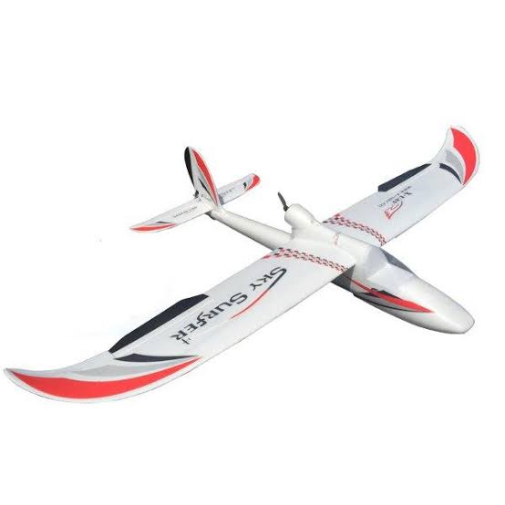
RC plane model that our team will be using for our first prototype will the Sky Surfer X8 with a wingspan of 1410mm. This plane model is a high wing trainer plane, high wing plane generally has low center of gravity which would promote good lateral stability. A plane would with good lateral stability would help to overcome side slip and correcting rolling moments. Which would be beneficial for first time RC plane flyers like us.

The Sky Surfer X8 is also a pusher plane, where the motor and propellers are mounted at the back the plane. There are various benefits from this configuration.

  • The propeller is well protected. In the event of nose landing or unfortunate crashes, the damage to the motors would be at minimal.
  • It would not obstruct the view of our FPV.

The EPO (Expanded PolyOlefin) material of the Sky Surfer also makes maintenance and repair easier.

Motor & Propellers:

The suggested configuration of the Sky Surfer X8 is a A2212 KV2200 brushless out runner motor paired with a 6 X 4 APC propeller. However, to increase the efficiency and thrust of the plane, we have decided to upgrade the motor with a Dual Sky ECO2814 (1330kV) brushless out runner motor paired with a 7 x 6 APC propeller.

However, the current airframe only support up to 6 inch propeller, hence we will be getting a motor mount to further enhance the performance of the motor by pairing the motor with a 7 inch propeller.

ESC:

Selection of ESC is based on our motor selection. Hence for the Dual Sky ECO2814 (1330kV) the suggested ESC in the datasheet the max current draw is at 36.9A. Hence the ESC chosen is a XRotor 40A ESC.

Servo:

The recommended servo is a 9g servo, however the servo that came with the kit is a plastic gear servo. Plastic gears servo are more likely to strip if the motor is jammed or overloaded. Compared to metal gear servo which are longer lasting. We then decided to go ahead with the EMAX 12g Metal Gear Servo.

LiPo:

Battery Capacity is mainly determined by the motor choosen. Hence, with reference to the datasheet of the Dual Sky ECO2814 (1330kV, we have decided to use the Turnigy nano-tech 2200mah 3S 35~70C w/ XT60.

Lipo Alarm:

The lipo alarm is a device to be plug into the lipo balance lead. It will release a “alarm” when the LiPo voltage falls below 3.3V.  Which is essential in notifying us when the voltage is low. 

Video FPV:

Spotter V2 attach with a build in transmitter of 5.8GHz

Posted in UAV