First Flight

As Kanesh had deemed me and Isaac competent enough to fly the plane after going through a simulator test, it was now time to go out to the field for actual flights! Together with the delivery drone group, we met up with Kanesh at the Old Holland Road flying field on a lovely sunday morning

From left: Justin, Kanesh, Isaac and Kae

I was really nervous and my hands were trembling when the plane was launched by my groupmate. Although I had prior experience flying quadcopters as a hobby in my polytechnic days, fixed wing aircraft was a different ball game altogether. My reaction had to be many times faster as the aircraft has to be constantly in forward flight in order to stay airborne – unlike quadcopters which can hover. What’s more, flying circles meant that there are times when the plane’s nose will be facing me directly: meaning that the alieron inputs are essentially inverted!

Crashing in real life also meant a lot more downtime fixing the aircraft than crashing in the simulator.

Sure enough, the first few flights almost ended up in disaster as I was not used to controlling the airplane and nearly flew into one of my groupmates. I struggled to control the plane as it was pitching up and down wildly.

Something that exacerbated my bad flying was that I did not quite know how to trim the aircraft while in flight, because doing so would require me to take my thumbs off the control stick and move the trim switches, which was something I was not confident of doing. Alas, the plane few nonetheless and I was quite happy that I managed to learn some flying.

This session lasted quite a short while as the weather took a turn for the worse and it started to rain for the rest of the day, and this concludes the maiden flight of our group’s Skysurfer.

Completed PCBs and Preliminary Tests

The PCB finally arrived earlier this week and the team has assembled a total of 5 boards. I opted to systematically hand solder the PCB first while individually testing various parts of it. By doing so, I was able to confirm the hardware works as expected and troubleshoot it easily. Here are the photos of the completed board.

Good news! All the individual component works as expected. (after some troubleshooting 😶)

The PCB was soldered and tested in the following order:

  1. Buck converter
  2. Digital 3.3V supply
  3. USB to UART converter and USB
  4. ESP32
  5. SD Card
  6. Analog 3.3V supply
  7. ADC and supporting components

Total time taken was roughly 6 hours.

Preliminary Tests

Let’s take a look at the performance of the hardware.

Power Supply

The power supply unit (PSU) on the right is feeding power into the main input of the PCB and the multimeter is measuring the output of the 5V buck converter. This shows that the buck converter is able to produce a 5V output (with a ~0.8% error) even when fed with 6V input.

Note that this test is conducted when the ESP32 is on idle, ie low load. This should be considered the absolute minimum voltage and not the operating voltage.

ADC

Next, we’ll take a look at the accuracy of the voltage reference.

The accuracy of the ADC is directly dependent on the accuracy and stability of the voltage reference.

The multimeter is measuring the output of the voltage reference after passing through a low pass filter (LPF). As shown, the voltage is spot on at 2.045V. As we currently do not have the capabilities to perform any form of noise measurements on the voltage reference. Also, we will skip the ADC performance test for now.

ESP32, USB and SD Card

Justin has written a test program to write a file into the SD card and read it back.

This ensures that:

  1. The USB to UART converter is working and is able to program the ESP32 with no issue
  2. The ESP32 is functional
  3. The SD card is functional

The SD card is mounted successfully, and read and write operations are successful.

BME280

Screenshot by courtesy of Justin.

As shown in the above screenshot, the ESP32 is able to read the temperature, pressure and humidity respectively.


Issues in Hardware

Hotplate process produced inconsistent results

After I hand soldered and confirmed that the PCB is indeed working, the team proceeded to use hotplate to reflow 4 other boards. There were however, different issues with different boards, with different ICs either not soldered on properly or has pins that were shorted together.

The team has concluded that this was due to the process not being optimised for reflowing. This could be due many factors such as, the kind of solder paste used, the thickness of the stencil, the size of the pads etc.

This required additional rework after the reflow process.

Programming of ESP32 with SDIO lines pulled up

IO2 of the EPS32 is a bootstrap pin, meaning that this has to left floating in order to go into programming mode…….. Only if you’re programming for the first time.

We noticed that some boards couldn’t be programmed. However, there wasn’t an issue with the schematics. Turns out desoldering the pullup resistor on IO2 before programming for the first time worked. Thereafter, the pullup resistor had to soldered back in, in order to use the SD card. We suspect this might be due to the ESP32 internal efuse not being programmed from the factory.

High Quiescent Current Draw

Quiescent current is the current that a device draws when it is in idle mode. In our case, with everything powered down, we have ~6mA current draw at 12V. That works out to be about 15mA at 5V. While the ESP32 is capable of very low power draw, down to 0.1mA in power saving mode, this would not matter if everything else on the board is drawing 15mA.

After some quick probing on the board, we have determined that the current draw comes from:

  1. Low Dropout Regulator (2x 5mA)
  2. LEDs (2x 2.5mA)

We have placed an order for new low quiescent current LDOs. However, for the next revision of hardware, low current draw will one of the main focus.

Missing USB power diode

During the process of PCB design a diode to provide provide to the board from USB was unintentionally left out, as a result, the board cannot be powered from USB. This was quickly solved by soldering a ‘botch’ wire from the USB connector to the 5V supply.


Next Steps

We will be looking at how we can optimise the current design over the one or two weeks. Stay tuned for more details!


Edit 22 Aug 2020

Issue with the Programming ESP32 with SDIO Lines Pulled Up

It appears that our conclusion that this issue only occurs when programming for the first time may not be entirely true. Some boards can’t be programmed with IO2 pulled up regardless it is the first time or not. This issue can be fixed be allowing the software to control the pull up. However, changes has to be made on the hardware.

One of the changes for the next revision, we will be connecting the pull up to the SD card power, rather than the main (always on) power.

PCB Status Update

After some discussion within the team, we have finished the design work of the PCB.

The next 2 pictures shows the preview of the PCB.

Overview

Let’s take a closer look at the details.

The boxes represents the various sections of the PCB. They are numbered anti-clockwise from the top left.

1: Analog to Digital Converter (ADC)

This section consists of the ADC itself, a 24 bit Microchip Tech part, and a 2.048V voltage reference.

2: Air pressure, humidity and temperature sensor

Sensor onboard is a BME280

3: Analog Power Regulator

We will take a closer look at the power supply considerations later.

4: User Button

5: GPS header

GPS is connected to UART 1 of the ESP32

6: Micro SD Card

SD Card is connected to SDIO of the ESP32. Propagation delay of the traces are matched to within 25ps of each other.

(Probably an overkill but why not?)

7: Main Power Regulator

8: On Board Programmer

9A: ESP32, a WiFi and Bluetooth capable module

9B: Antenna for ESP32

The antenna is designed to hang outside of the board for optimal performance.

Power

Power is supplied from a 6-12V source – a 2s LiPo or even single lead acid battery.

A DC-DC buck converter was used for high efficiency.

In order to provide smooth power for the devices on board, 2 sets of low dropout linear regulators (LDO) are used.

The 2 LDO supply analog and digital power as shown in the above diagram.

Analog and digital power are supplied separately in order to prevent fast switching digital circuits from introducing noise in the analog circuits.


ADC

The ADC, Microchip MCP3561 , has 8 differential inputs – 4 channels.

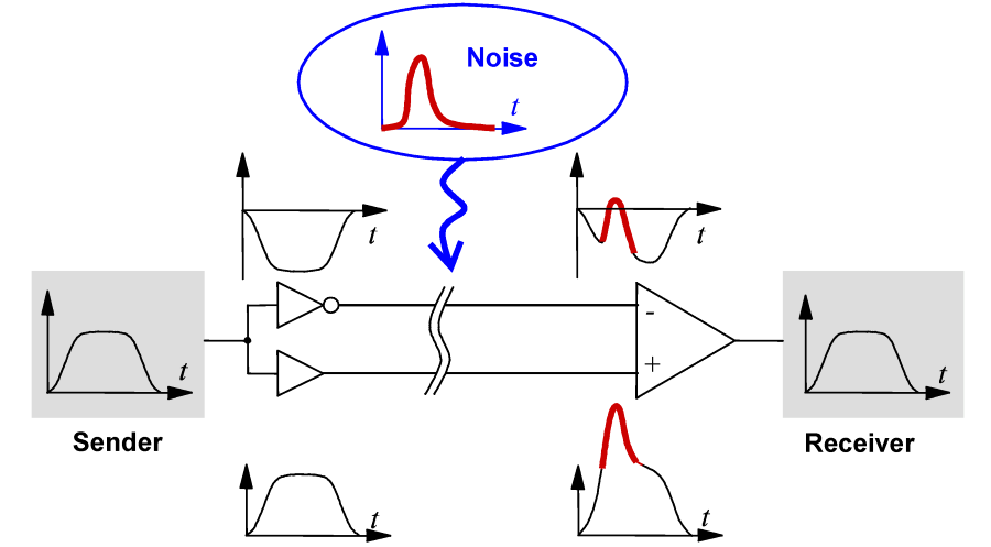
In a differential signal, the wire pairs are twisted, hence any noise introduced will be introduce into both of of the individual wires.

By measuring the voltage difference in the pair, any noise introduce is effectively cancelled out.

Explanatory diagram showing how differential signaling works

Image by courtesy of Altium (https://www.altium.com/documentation/altium-designer/differential-pair-routing-ad)

Supporting the ADC is a Microchip MCP1501T, generating a 2.048V voltage reference for the conversion.

The MCP1501T was chosen for it’s stability over a wide range of temperature and it’s regulation capabilities (this is a topic I will not go into).


Temperature, Humidity and Pressure Sensor

BME280 was chosen for as it is integrated (3 in 1), speaks both I2C and SPI, and has a library written for it.

Since this is an analog sensor (with a digital interface), the BME280 is powered from the analog supply.


Analog Power Design

Layer 3 of PCB, showing the analog power plane

In order to maintain extremely low noise in the analog supply, separate copper pours was used for both digital and analog supplies.

Care was taken such that any analog or digital signal does not cross out of it’s own power plane. (with the exception of channel 4)


ESP32

The ESP32-WROVER-IB is chosen as it has the option for an external antenna through it’s IPX (1st gen) connector.

A small section of the PCB is cut out for the antenna of the ESP32. This ensures that the tuning of the antenna is unaffected and the antenna can radiate properly without any obstacles. This ensure that the tuning of the antenna is not affected by the PCB.


Conclusion

The above is a summary of the main considerations in the design and layout of the PCB. Much time was spent selecting parts, discussing what is important and what is feasible. All while trying to keep within reasonable time and cost.

The design has been sent for fabrication on the 3rd of August. In the next post we will be taking a look at the assembled PCBs.

Protocol Optimisations

As mentioned in prior posts, we implemented a protocol based off TFTP, which we call Modified Trivial File Transfer Protocol (mtftp). The diagram above illustrates how it works:

  1. The Client (collector on the UAV) sends a Read Request (RRQ), which specifies what file (file index) and where in the file (file offset) to transmit. A window size is also transmitted which indicates how many data packets the Server should send before waiting for a response.
  2. The Server then sends up to window size DATA packets to the Client (the end of file (EOF) is indicated by sending a partial DATA packet, or zero bytes if the file size is a multiple of block length).
  3. The Client then sends an Acknowledge (ACK) packet with the block number of the largest block it successfully received.
    1. This allows for correction of missing blocks: for example, if the Client receives block number 0, 1, 2, 4, 5, 6, 7 with a window size of 8, the Client can detect that block 3 is missing, sending an ACK for block 2.
    2. If the Client receives a block of less than 247 bytes, this indicates the end of file. For example, if the client receives block 0, 1, 2, 3, where block 3 contains 200 bytes, it will not expect any further blocks and sends an ACK for block 3.
    3. If the final block in a window (ie block 7 when window size = 8) is missing, the client will never know that the window has ended. In this case, both the client and server will timeout after a short delay, terminating the entire transfer.
  4. If EOF has not been reached, the Server then advances the file offset by the number of bytes acknowledged, then starts a new window with block number 0.

We use the following terms:

  1. Block – A single chunk of data in a DATA packet. The maximum length of a block is fixed to 247 bytes in our application since ESPNOW has a maximum payload length of 250 bytes, and we use 3 bytes (1 for opcode, 2 for block number) as a packet header.
  2. Window – Transmission of up to window size DATA packets before a response is expected from the client.
  3. Transfer – The transfer of multiple Windows to transfer a file until EOF.

Initial tests demonstrates that the above works in close proximity, but when the Client and Server are far from each other in an urban environment (SPMS Atrium), packet loss is non trivial. As mentioned above, if the Client receives block 0, 1, 2, 4, 5, 6, 7, it sends an ACK for block 2 and the Server starts transmitting the data at block 3 again. This is wasteful – the Client has already received data for block 4, 5, 6, 7.


The flowchart on the left illustrates the initial implementation of the mtftp client. Solid lines depict flows involving actual packet transmission. Blocks received in-order are written to disk (block numbers 0 and 1 in the example at the bottom). However, when a block is missing (block number 2), all future blocks are discarded (block number 3, 4, 5, 6, 7, 8) because we cannot save it to file – there is no guarantee we’ll receive the missing block, and even so, we would need a way to mark that block as missing. Rather, the client sends an ACK for block 1 (the last in-order block received) and the server resumes transmission at block 2. This is obviously inefficient especially when the window size is large, say, 32 blocks. If block 1 is lost, 30 other blocks that may be received successfully are discarded.

Our solution to this is to introduce re-transmission – missing block numbers are stored and subsequent blocks are buffered. This is illustrated by the yellow blocks in the flowchart on the right. At the end of the window, the client transmits a RTX packet containing the missing block numbers. The server then re-transmits these blocks, and the client writes the initially missing blocks along with the buffered blocks to disk. This eliminates the issue described above.

However, there is still another issue here – if the RTX or ACK packets (depicted by the thick black lines in the flowchart on the right) are lost, the communication times out. If it was a RTX requesting for one of the earlier blocks in the window, most of the window will be discarded again. A possible fix for this is for the client to re-transmit a RTX or ACK should communication time out in at this portion. However, a quick implementation proved to be buggy and was reverted. We will revisit this issue later as we we would like to implement other functionality first.

Bad Chinese Quality Control Strikes Again!

Finally the time came to transport our two Skysurfers to NTU and have them assembled. We opened the box excitedly like children opening Christmas presents. This excitement quickly turned into dismay when I realised that the dents in the retail box extended into the airplane foam, causing major deformation. To add insult to injury, the damage did not just occur in obscure, unimportant areas; there was major damage to the critical areas of the airframe also! Bummer!

Damage to the wing’s leading edge


Wing deformed


More damage – even the aileron was not spared

Fortunately, we bought two airframes so the second one was less damaged and in a more flyable condition. Hence, we chose to assemble that first.

However all was not lost, upon inspection by Kanesh, he determined that the faulty airframe could still be salvaged by flattening out the deformed parts with some weights.

Professor Google also recommended soaking the foam in hot (preferably boiling) water to have it expand. Problem was, the airplane was larger than any pot we could find. Thus, we had to settle for the second best option of pouring boiled water over the foam and then bend it back into its intended shape.

Found a kettle in the MnT lab…

And so began the painstaking work of letting the hot water soak into the foam and then slowly bending it back into its original shape, then putting a really heavy weight on it

Using one of the many discarded power supplies in the MnT lab as a weight to crush the foam back into shape

After a few hours of work, success! The wings are now back in an airworthy condition!

[TODO: add photos of wings after repairs]

Synchronising Sample Time

One of the objectives we have been working towards is ensuring samples from different nodes are time-synchronised (ie sampled at the same point in time). As mentioned here, GPS receivers are one method to obtain accurate timestamps.

The commonly available U-blox Neo-6M GPS receiver outputs a 1 Hz timepulse, which is configurable between 0.25 Hz to 1 kHz. It would be entirely possible to configure the timepulse frequency to match our target sampling frequency, then use an edge of the timepulse to start sampling. However, keeping a GPS receiver constantly powered on has severe implications on battery life.

As presented in Multi-Channel Data Acquisition System with Absolute Time Synchronization:

Measurement of the last (1000th) sample within a given second disables the timer/counter reset (it still increases every clock cycle) and introduces the microcontroller into the awaiting mode (waiting for the next synchronization pulse). When the pulse arrives, the timer/counter value is first read and then it is immediately reset. If the local clock has its nominal frequency (48 MHz), the read value should be equal to C, which corresponds to 1 ms. If it is not, the difference between C and the number of measured cycles is used to adjust C. This technique compensates for possible drifts of the local-oscillator frequency, i.e., it ensures that recorded samples are uniformly distributed over time with 1 ms spacing between them.

We can tweak this slightly by assuming that the drift of our local oscillator is relatively fixed and will not change that rapidly. This allows us to compute C periodically, say, every hour by powering on the GPS receiver, getting a few timepulse edges, then powering off the GPS receiver. The sampling rate until the next synchronisation to GPS time will then be based off the computed value of C.

The use of an ESP32 here complicates things:

  1. Hardware timers are available. Although these timers support periodic mode (ie fire a ISR at a certain interval), they are clocked by the APB clock which may not be stable over time.
  2. A RTC timer is available, which supports the use of an external 32.768 kHz crystal, but there is no support for using this timer to fire interrupts on the main SoC

With these constraints in mind, we propose the following method of synchronising the time at which sensors are sampled:

  1. Start a hardware timer
  2. Wait for at least 2 timepulse edges, store the difference of hardware timer value at each edge as C
    1. Set system (RTC) time based on the timepulse and NMEA sentences (use this to mark time when storing samples)
  3. C represents the number of timer counts (based off APB clock) in a 1 second interval, start a periodic hardware timer with period = C / target sampling frequency
    1. Configure the periodic ISR to start sampling of sensors

A quick experiment suggests that for the particular ESP32-DevKitC that was used, C is approximately 999990:

I (81745) sampling_task: pulse: 81362899
I (82745) sampling_task: pulse: 82362890
I (83745) sampling_task: pulse: 83362880
I (84745) sampling_task: pulse: 84362870
I (85745) sampling_task: pulse: 85362860
I (86745) sampling_task: pulse: 86362850
I (87745) sampling_task: pulse: 87362840
I (88745) sampling_task: pulse: 88362830
I (89745) sampling_task: pulse: 89362820
I (90745) sampling_task: pulse: 90362809
I (91745) sampling_task: pulse: 91362799
I (92745) sampling_task: pulse: 92362789
I (93745) sampling_task: pulse: 93362779
I (94745) sampling_task: pulse: 94362769
I (95745) sampling_task: pulse: 95362759
I (96745) sampling_task: pulse: 96362749
I (97745) sampling_task: pulse: 97362739
I (98745) sampling_task: pulse: 98362729
I (99745) sampling_task: pulse: 99362719

The observed drift of approximately 10 us every second would result in 36 ms of drift over 1 hour, and 864 ms over 24 hours. Given that our target sampling frequency of 80 Hz has a period of 12.5 ms, if uncorrected, this drift would be an issue.

Further testing for a longer period of time is necessary to establish whether the amount of drift is constant (and probably temperature dependent). Exploring the drift of the RTC clock (once our PCBs with a RTC crystal arrive and are assembled) may also provide alternative possibilities for synchronisation.

Oversized Shipping Woes

It has been about 3 days since plan B (which involved us buying the airframe from Taobao) was activated.

As Cainiao’s forwarding warehouse was in Dongguan while the Skysurfer was dispatched from Wenzhou, we expected shipping to take some time due to the huge distance. We were thus pleasantly surprised at how the package consisting of two aeroplanes made it halfway across the country in half a day.

Wow!

Mad respect to Yuantong Express for the speedy delivery!

However, we were extremely dismayed to learn that our package had exceeded the maximum permissible dimensions for ordinary air shipping! What a bummer!

Love letter from Dylan from Zhongtong Express

Translation courtesy of Professor Google:

Hello, this is Zhongtong Taobao Collection Warehouse.
Please read the following carefully:

Your parcel (waybill number: YT4661635916747) cannot be consolidated because it exceeds the official Taobao shipping size regulations.
You can choose to return the package by express or transfer this package offline, and use Zhongtong Container Lines to continue the transshipment, and you need to pay the overseas freight of this package.

Air freight: The freight is RMB [396] and the time limit is 7-10 working days;
Shipping: The freight is RMB [137], and the time limit is 17-20 working days;

If you need to continue the transfer, please contact WeChat customer service WeChat account 16573409665
Official size regulations: The length of one side (length/width/height) should not exceed 80CM, and the sum of three sides (length + width + height) should not exceed 150CM.

If the package is not processed within 36 hours, it will be returned. If you have any questions, you can contact WeChat customer service: 16573940965 or contact Zhongtong Container Lines online customer service
Remarks: If there is no reply to this WhatsAPP, please contact WeChat customer service 16573940965
Remarks: Because WhataAPP is unstable, it may cause inconvenience to you. Please understand

Note: You can’t pay here, you can pay at Taobao shop in WeChat customer service
Remarks: If there is no WeChat, please contact the seller to let the seller contact the customer service of the warehouse. Thank you for your cooperation

If the WeChat customer service does not reply in time, please wait patiently, thank you, wish you a happy life

Â¥396 for air shipping! That’s around S$80! Outrageous! But oh well…we were working against time and would rather pay for faster shipping. So after explaining our predicament to Dr Ho, he allowed us to opt for the more expensive but faster air shipping. Hooray! After spending some time negotiating with Dylan on WeChat, we managed to make payment for oversized shipping. Here’s to hoping that it will arrive as soon as possible…

Behold, our premium shipping😢


Speed Optimisations

The below speeds were observed using a SanDisk Ultra 16Gb A1 MicroSD Card on a hand-wired prototyping board with 2Mb files.

The very first iteration of the readFile function was an naive implementation:

  1. Open file pointer to the requested file
  2. Seek to the requested offset
  3. Read requested number of bytes
  4. Close file pointer
  5. Return data

This was slow: it took 11953726 to transfer 1048579 bytes (85.6kbyte/s).

The obvious optimisation that can be made here is to persist the file pointer between calls to readFile:

  1. Check if file pointer is open, if the current file pointer is for the correct file
    1. If not, close the current file pointer and open the requested one
  2. Seek to the requested offset
  3. Read requested number of bytes
  4. Return data

This improved speeds slightly to 124.2kbyte/s.

We can make use of a byte buffer to buffer data from the SD card, allowing us to read in large chunks:

  1. Attempt to read requested number(usually 247) of bytes from the buffer
    1. If successful, return data
  2. Else, read (up to) 8192 bytes from the SD card and write it into the buffer
  3. Read up to requested number of bytes from the buffer again
  4. Return data

This improves speeds to 229.8kbyte/s.

To prevent buffering too many ESP-NOW packets (or Wi-Fi memory allocations start to fail), code was written to track the number of buffered packets. This code issued a 10ms delay if there were too many buffered packets. It was observed that most of the time after the delay, there were 0 buffered packets left. This means that the 10ms delay might be too much, resulting in dead time where no more data was being sent. Removing this delay improved speeds to 338.8kbyte/s.

While writing this post, we came across this comment which suggested using setvbuf to buffer reads. Using this over our home-brewed ring buffer solution improves speeds substantially to 440.7kbyte/s. This isn’t too far from the 549250bytes/s we observed when testing transfers speeds without doing any processing, though we need to test this out in the field to confirm its performance.

File Transfer

Now that we’ve started on the protocol for file transfer, all we have to do is to attach it to ESP-NOW and the SDMMC controller for data transmission and retrieval respectively as illustrated in the diagram below.

We soldered a quick prototype of a SD Card socket connected to a ESP32-DevKitC:

For the software, we add another layer over mtftp to manage sessions: the collector broadcasts a synchronisation packet. The node(s), upon receiving this packet, echos this packet back to the collector and adds the collector as an ESP-NOW peer (necessary for unicast communication between two ESP-NOW devices). Upon receiving the echoed synchronisation packet, the collector also adds the node as an ESP-NOW peer and hands over control to the mtftp handlers.

Output from the node (top) and collector (bottom)

The software discussed above can be found here.