
Initial Phase
The original plan for this project was to have a 5-sided box which could detect a ball bouncing in it. As such, we decided to work with this fact and sourced for possible ways to detect the ball bounces.
Possible Ideas
- Touchscreen
- Force sensitive pressure sensor
- Arduino push button
- Piezoelectric sensor
Eventually, after much deliberation, we finally agreed on using piezoelectric sensors as the medium for detecting the ball bounces because we felt that they fit the criteria for our project: Cheap, Easy to use and Flexible. Now, with the type of sensors finalized, it was time to construct a box that could house these piezoelectric sensors.
Prototype
Based on our ideas and discussion from the initial phase, we began the designing prototypes of the box and ramp on Autodesk Fusion 360. Due to the lack of commercial options (we were told by suppliers who got back to us that this project was difficult and challenging), we decided to instead try out prototyping using 3D printing first.
Box Prototype 1:
Our first design is loosely based off a child’s toy, “Connect4”, whereby the box would be designed with holes and slits on each wall to allow the piezo sensors to be slotted into it, just like the children’s game. The motive was to allow for the surface of each side of the box’s wall to be covered in piezo sensors, such that when the ball bounced off the sides, it will be in direct contact with the piezo sensors and register a reading.

Figure 1: Image of the game “Connect Four”
The box has a dimension of 31.8 x 31.8 x 31.8 cm, with 16 circular holes (Diameter: 24 cm) spaced regularly on each side of the box, with a 2mm slit on each side to slot in the piezo sensors.

Figure 2: Box Prototype 1 with circular holes
However, we realized that the piezo sensors themselves were very small in size, and in order to ensure that the sides were adequately covered, we decided that we could not simply just cover the walls with piezo sensors. Instead, we found a way to allow the piezo sensors to be able to detect the bounces and still cover a significant surface area through the use of a proxy element.
Box Prototype 2:
After further discussion and experimentation, we noticed that placing a sheet of material in direct contact with a piezo sensor will still enable the bounces to be detected, even if the bounces were on the material itself rather than the sensors. With this new knowledge in hand, we went ahead and redesigned the box to fit our new key element instead. The round holes were enlarged and changed into a square hole since it was agreed that a square piece element would be uniform and easy to reproduce and install. To circumvent the problem of insufficient support for the box to stand on its own, the square holes had to be designed not to be too small, and after rounds of measurement, we finalized each square hole to be 46.6mm x 46.6mm large, while our individual element piece would be 45mm x 45mm large.

Figure 3: Box Prototype 2 with square holes
Final Box Prototype:
Eventually, we discovered a flaw in our 3D model, in that it would be highly unfeasible to print the whole box. Instead, we decided to simply print the walls of the inner skeleton, as shown below, and assemble them in another pre-made box which will hold them in place. Due to the lack of variety in commercial options explored, we had to settle on a pre-determined dimension for the outer box (12-inch x 12-inch x 12-inch acrylic box; 12 inch = 304.8mm) and base our new 3D model off these specifications. Understanding that we required some leeway between the inner 3D printed box and outer acrylic box, the 3D model was designed with the following details: 298mm x 298mm x 298mm with 46.6mm holes and a 3mm thickness.

Figure 4: Final Box Prototype with just the skeleton and original square holes
In order to hold the side walls in place, brackets were designed to be fitted at the corners where the individual walls met. Initially we did not account for the printing tolerance and the parts we received were a tight fit. We then decided to trim the brackets and make them shorter and thinner so as to achieve a snug fit but at the same time allow them to be removed easily without much effort. Due to the base wall having additional stands printed on the underside of the part, the base corner brackets were designed separately, hence the 2 designs that we have below.

Figure 5: Box Corner Bracket

Figure 6: Base Corner Bracket
Ramp Prototype 1:
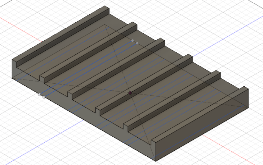
Figure 7: Ramp Prototype 1 with 1-degree of freedom
The first ramp design was a simple flat ramp with 5 lanes for the ball to roll down. The aim was to provide the users with a 1-degree of freedom by installing an adjustable jack stand below the ramp, as the users are able to vary the angle from 0° to 90°. However, the limitation of this setup was that the ball may not be able to reach certain areas within the box. With this in mind, we decided to improve on the ramp by increasing it to achieve 3-degrees of freedom.
Final Ramp Prototype:
To achieve the ramp with 3-degrees of freedom, we designed a flat cylinder with holes and indentations. Slider nuts and screws were installed accordingly to fit protractors and an acrylic tube, creating 2 rotational axes and 1 translational axis. The slider nuts were selected as it can fit snugly to the steel profiles used to build the metal cage, enabling the translational movement along the profile. In addition, holes were specially designed into the ramp base to allow screws to pass through and secure the tube to the base. This ensures that the bottom surface of this component is smooth and has no protruding parts since this face will be sliding along the metal rails.

Figure 8: Ramp Base
Rail System Prototype:
The metal cage was designed to encompass the acrylic box and its contents, and to provide a rail system that grants the ramp freedom to move in the lateral direction. Since we had already measured the dimensions for the acrylic box, finalizing the specifications for this metal cage was not difficult as they had to be the same size as the acrylic box.

Figure 9: Metal cage and rail system