
3D Printing
Assembly of Parts
One of the things we learnt was how to split our CAD designs into parts to optimise the printing process. For our 3D printed cage, we initially wanted to print the entire box as a whole. However, the entire process would take too long and the support required for the box was even more than the actual cage itself. This prompted us to think of other alternatives, which included considering another design (e.g. round holes instead of square holes would make the 3D print more sturdy) as well as printing the box in parts. Ultimately, we settled for printing the box in parts as we wanted to make minimal changes to our design. This meant printing each box surface one at a time and securing the whole box together with 3D printed corner brackets. In this way, the box would require less support and the time taken to print the whole box would also be reduced.
Optimisation for Tight Fitting Objects
In designing the corner brackets to secure the box, we initially gave a 0.1-0.2 mm leeway so that the corner brackets could fit tightly. However, the fit was still not very good as the 3D printing was imperfect. As such we had to sand down the corners, but after a long while we still could not obtain a perfect fit. In the end, we decided to re-print the corner brackets with a tolerance of 0.3 to 0.5mm. This served as a useful guide which we could take away from for future projects.
Using 3D printing to overcome design limitations
We realised that 3D printing is a rather good solution to problems related to design limitations. One such instance would be having to elevate our screws for our ramp mechanism, but existing washers were too thin and did not allow us to elevate our screws by a desired amount. As such, we turned to 3D printing, which allowed us to print our own customised washer, hence overcoming this problem. Another instance would be how we wanted to construct our keys using acrylic and springs. However the cost of production of these keys was too high. In the end, we found out that 3D printing small “tables” would be a suitable alternative as the production cost was lower and the assembly method was also more elegant.
Hardware
We learnt how to use various tools to refine our 3D prints, such as deburring tools to cleanly remove the skirts off our 3D prints. We also gleaned an insight on how to use a drill and an electronic metal cutter to drill through our acrylic box and cut through aluminium profiles.
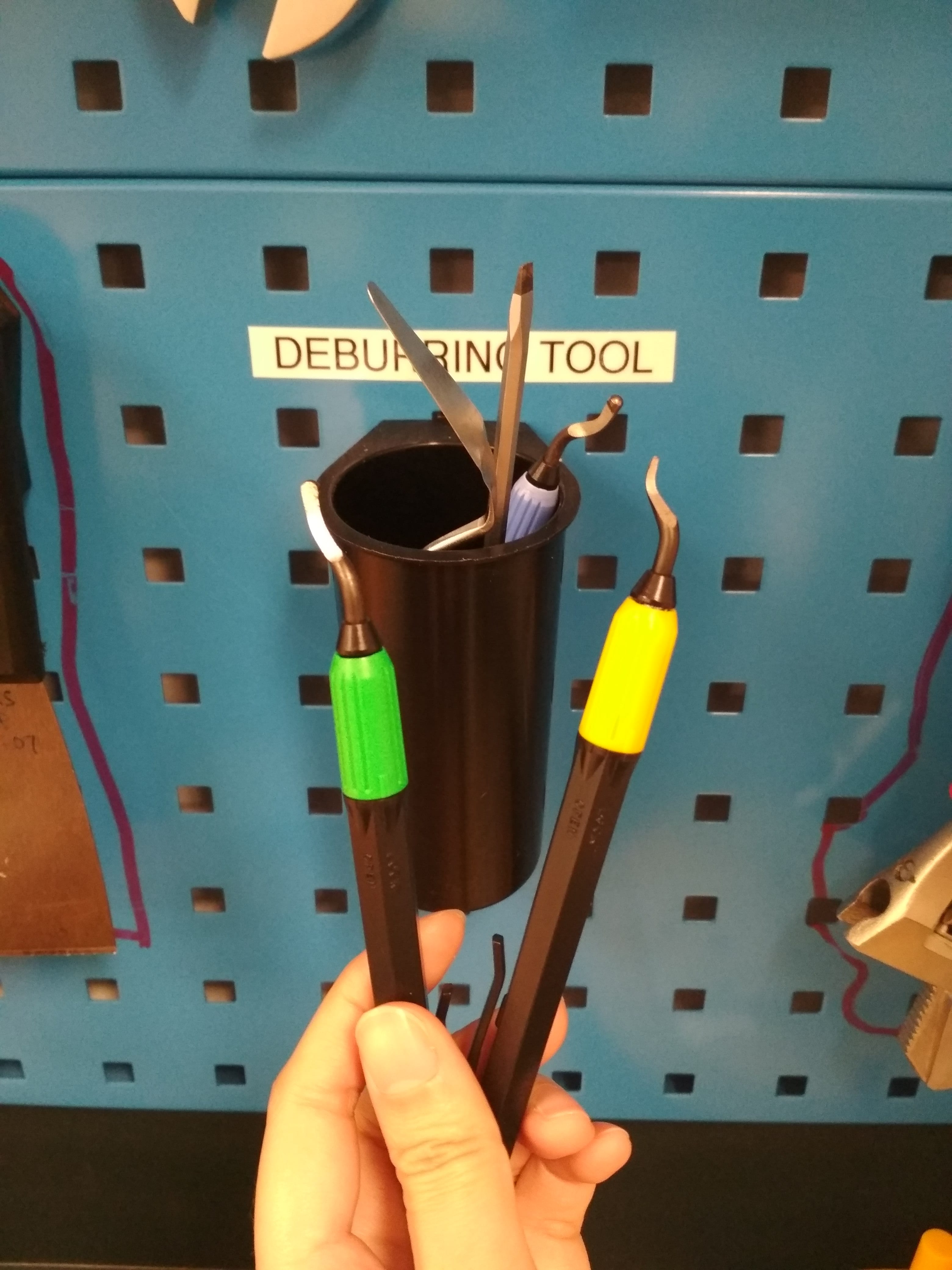
Deburring tools
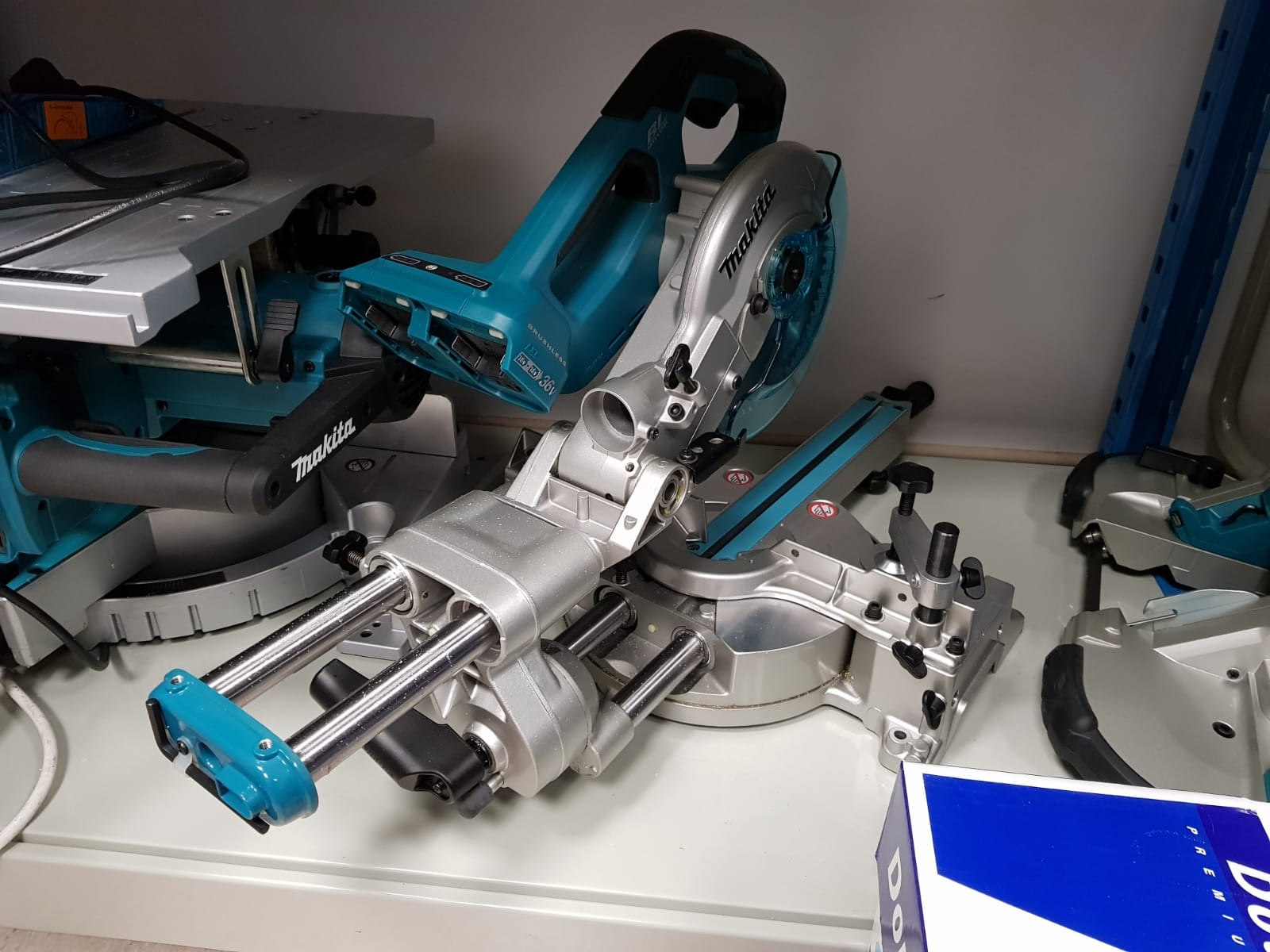
Electronic metal cutter
Additionally, we also better understood the different methods used to cut through different materials. For instance, we could not use powerful electronic metal cutters to cut through acrylic, lest it breaks. However, normal cutters also could not do the trick as they would be too weak to cut through the strong acrylic. In fact, the lab lacked the appropriate tools to cut the acrylic, as such we had to source for external suppliers.
Electronics
Multiplexing
We learnt more about multiplexing as a technique to reduce the number of signals received by the micro controller. This made our programming of the system more simplified.
Programming
We learnt how to use Arduino libraries in our code, as well as other Arduino components such as LCD screens and piezo elements. We also familiarised ourselves with adapting our algorithm to the set-up and loop structures of Arduinos.
Others
Making use of existing resources available
One of our key takeaways was learning how to make use of existing resources to construct our project. This not only cut cost and saved time, but also reduced unpredictability as we could immediately experiment with exiting resources to see what worked for our project and what did not.