Meeting 30 👨‍💻

29/07/2019  

Agenda 

  • Mount everything on tank in their proper spaces 
  • Solve any unforeseen problems  


Tasks accomplished: 

  • Mounted electronics and things on robot 
  • Bought a new passive to active adapter and a new switch from Sim Lim  


Okay… so basically, the previous day, while we were stress testing the robot on our own, we fried the passive to active adapter and the switch because we connected the wrong cables to the IN and OUT ends of the adapter and our two main components fried. Without the switch, we cannot power most of the electronics including our camera and transceiver. Without the adapter, the transceiver is not powered up properly.  😭😭😭

To salvage this, we cabbed to Sim Lim the first thing in the morning to source for these new parts and fortunately, we managed to find the parts and get the tank to work again!  

We then mounted the electronics on the tank and well… it does look good!  👍👍👍

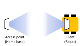
We had to finish up our slides while trying to overcome the servo motor code problem (which we feel that it may be due to a lag time observed during extraction of signal strength from the transceiver webpage when running the code). This results in some problems during calibration of the turntable angles and getting the turntable to face the right way for better connection. We tried but have not yet managed to solve the problem but we had to continue prepping for the presentation the next day and hope things go well!  

Before we forget, here is a picture of our final product! 

Final Product

Here is also a video of testing out our final product with the live stream video and audio. It is a successful test as shown in the video (1.12-1.30) where Jing Xuan is able to see and hear Ming En asking her to stop and make a U-Turn to go back into MnT lab. [Evidence can be seen in the live stream footage on the laptop screen] 


While not all things worked out perfectly in the end, we managed to achieve most of what we wanted at the start – essentially the audio, video and movement of robot. What we did realise throughout this journey is that nothing is easy and robotics is hard but when we come together with our best efforts, we can ultimately make things work some way or another.  This project cannot be completed without the help of Tony, Kelvin, our friends and all our teammates. Thank you for making this project an enjoyable yet fulfilling learning experience!  

Group Photo with Tony

Meeting 29 🙀

26/07/2019 

Agenda: 

  • 3D printing of robot parts
  • Solve any unforeseen circumstances


Task accomplished:  

  • Printed component holders for robot (RPi, PoE adapter + USB hub, buck & boost converter)
  • Started print job for robot casing
  • Re-soldered and heat shrunk any loose wires 
  • Discovered that the code to turn servo motor is not working well and attempt to solve by recoding 


Today, we asked Tony to help us with the printing of our robot casing which was necessary considering how messy and dangerous our wires were without a casing. Due to the sheer size of the print, we needed to use the Builder Extreme 2000 printer, which required Tony’s assistance and permission.


3D design of casing and electronic holders


While waiting for the long print, we re-soldered and heat shrunk any loose wires or connections. At the same time, we continued stress testing the robot and realised that the code to turn the servo motor by extracting signal strength is not working well as sometimes the transceiver ends up facing a direction that is not the direction of the highest signal strength. We had to change the code several times but had not managed to overcome this problem.  

After the casing was printed, we mounted all the electronics on the tank and you will get to see how our robot looks like on our last post next week! 🤭 🧐 🤓

Meeting 28 👷‍♂️

25/07/2019 

Agenda: 

  • Settle servo motor wires
  • 3D printing of holders and casing for robot


Task accomplished:  

  • Crimping and testing of DIY RJ45 cable for the slip ring
  • Soldering and heat shrinking of jumper cables to remaining slip ring wires for IMU
  • Started prints for component holders (switch, camera and secondary platform)


In the morning, Rachel made a trip to Sim Lim Square to procure an RJ45 wire crimper and wire tester for our group (after many valiant attempts of self-sourcing them)! 🤩

 
RJ45 cable tester and wire crimper


Since the slip ring comes with 18 individual wires as shown previously, we would need to crimp 8 of them to DIY our own LAN cable to insert into the client transceiver (rotary side) and switch (stationary side). We only managed to get the wires to work after multiple failures, even though we had 3 people performing the task 😅😅

Finally getting the crimp right!


At night, we then attached 5 male jumper wires to the stationary side of the slip ring, and 5 female jumper wires to the rotary side, for connection between the RPi and the IMU. We also started several 3D prints for holders to secure the components in our tank.

Meeting 27 👻

19/07/2019 

Agenda: 

  • Audio stereo live streaming to improve clarity 
  • 3D printed new transceiver holder with gear to run the servo motor 


Task accomplished:  

  • Audio stereo live streaming to improve clarity 
  • 3D printed new transceiver holder with gear to run the servo motor 
  • Design and 3D print slip ring holder 
  • Continue to code for signal strength  


We tested and checked the audio stereo live streaming and 3D printed new transceiver holder with gears to run the servo motor. We printed different versions of transceiver holders and finally settled on the following after printing and trying out the different versions.  

Screenshot of final design of 3D design for gear system and transceiver holder
 

The above designs for the transceiver holder and gear system works best because the gear on top of the servo motor is smaller than the one turning the transceiver so more and faster turns on the servo motor gear will cause a smaller angular but more stable rotation of the gear of the transceiver holder. We tried the different designs and the one in the screenshot above gave the most stable and best rotation with the least friction and least number of times when the gears actually got stuck.  🤔

And… we are off to our CNYang Freshmen Orientation Camp for most of the next week but we have to be back to settle the final details and ensure that things do work in case of hiccups.  😵

Meeting 26 🙂

18/07/2019 

Agenda: 

  • Work on live streaming of the stereo audio to improve clarity and eliminate x-runs errors 
  • 3D print new transceiver holder with gear system to run servo motor 
  • 3D deign slip ring holder 
  • Code to include signal strength in rotation of transceiver  


Task accomplished:  

  • Managed to eliminate x-runs errors by using the audio hat module we bought a while back (and thought we would not use!)  
  • Soldered and added a switch and LED light in our tank  
  • 3D printed new transceiver holder with gear to run the servo motor and slip ring holder 
  • Modified our code to extract and use signal strength in rotating transceiver 


The beginning of the day was met with several complication as one of our RPIs failed to work (screen black out) after we tried connecting the audio hat to the RPI. We were worried that we damaged the RPI as the undervoltage warning keeps appearing on screen before the RPI shuts down. Previously when we added to the RPI few weeks back, such problems did not happen. We had to reset the entire RPI (which means losing our audio code but fortunately all our other codes are back-up ed in the other RPI and we do remember most of the codes we used for our audio. 😪

After taking quite some time to get the audio to work like previous days, we tried using the audio hat again and the x-runs errors did disappear! Hooray! We managed to succeed in having good quality audio with a minimal lag time of approximately 2 seconds with the elimination of x-runs errors!

We also attempted to solder and add a switch to our robot so that we do not have to disconnect and reconnect the battery each time we want to off and on the robot. We tried adding a LED light to our tank so that whenever the LED lights up, it will signify that the robot is ready to go.

LED light


However, while we did add an LED light in the first place, we eventually removed the light because it was block by the casing and we found other ways to observe whether the tank is ready to be moved (eg when the transceiver finishes its calibration and stop turning or simply by looking at the code at the user’s end).  

We carried on coding for our servo motor using the following logic. Every time the tank moves away from its position, the transceiver will turn clockwise and if the signal strength gets lower, the servo motor will change direction and the transceiver will turn anticlockwise to attain a higher signal strength until the angle at which the highest signal strength for that location is detected. If the tank is simply moving on the spot, we will use the IMU to realign the transceiver back to its original angle to compensate for the angular displacement during rotation.  

Our logic of realignment of the transceiver appears to be reasonable but the codes do not always work as we face many problems with the calibration and sometimes lag time when trying to receive the signal strength. We will continue working on this! 🤗🤗🤗

Meeting 25 🙃

17/07/2019 

Agenda:  

  • Improve audio quality by reducing errors  
  • Rearrange components on the robot platform  
  • Work on coding for rotation of turntable 


Task accomplished:  

  • Rearranged components on the robot platform such that we put everything on the robot nicely and snugly while ensuring robot’s motion is stable (it won’t topple over) 
  • 3D designed a more comprehensive and stable platforms to accommodate all the electronic parts 
  • Coded to integrate extraction and use of signal strength in the re-alignment of transceiver when the tank is turning 
  • Designed new turntable to hold transceiver taking into account the position of slip ring to prevent entanglement and damage of wires and LAN cables 


We researched and tested out different variables/ changed some of the codes concurrently but those unfortunately did not help in improving the audio quality. 😕 😕 😕

For the hardware side, we had to reassemble the entire component so that we can lower the CG of the tank such that it will be more stable and less likely to topple due to inertia when moving. We aim to test this out the next day.  

Our slip rings arrived and as the deadline for the project nears, we plan to design a new turntable to incorporate the slip ring at the bottom of the turntable. However, this also indicates that we have to change the position of the servo motor (previously placed directly under the turntable). To make this happen, we have to come up with a gear system starting from the servo motor to eventually result in the rotation of the turntable since the servo motor is not directly attached to the turntable now.  

Slip Ring


At the same time, we also continued coding for the alignment of the transceiver to incorporate the use of signal strength in our code. However, we encountered the problem of the entire transceiver not working as the rotation of the transceiver did not manage to work as we wanted to. We did continue troubleshooting but the rotation did not follow the logic that we wanted to implement in our code so there is possibly some coding area where we need to refine. Stay tune to our next post where hopefully we manage to overcome these challenges 🤯🤯🤯

Meeting 24 🐵

12/07/2019 

Agenda:  

  • Continue testing audio to achieve live streaming and stereo effect (FFmpeg) 
  • Integrating angle measured by IMU with the strongest signal strength to turn the  
  • Started 3D-designing the casing for the tank to cover all the electronic parts so things do not fall over and the entire tank looks more marketable  


Tasks Accomplished:  

  • Managed to live-stream stereo sounds but had many alsa xruns errors which led to the audio being cut off and lag time of 4-5s (but this was reduced from the 9s we initially encounter and the sound quality for this is much better)  
  • Coded for the IMU to be integrated with the extraction of signal strength so the transceiver will know exactly how much and which direction to turn to achieve the most signal and best connections. 


Today… we finally live-streamed the stereo recording from our binaural microphones on a webpage  after an entire week of struggle! Initially we met with a lot of alsa xruns errors which meant the webpage/ vlc viewer where we input the IP address could not receive the data as fast as the rpi is transferring over. This led to a very high latency of 8-9s but after we changed the buffer_size (which we finally got it after googling the entire time!), we managed to reduce the lag time to about 4s and the quality is much better with much less pauses in between due to the smaller number of xruns occurred.  


Regarding the turntable and IMU, we managed to get the IMU working properly where we measured the angle that the transceiver turned with the tank from its original position and integrated this with the signal strength. The first step that we tried to do was to have a 360 deg scan for the strongest signal when the robot platform is stationary. Currently we faced problem of computational latency, so we tried to rearrange our lines in the code to ensure that both the best signal with the corresponding position (in terms of degree) were determined together for less computational lag and more accurate measurement obtained. We also modified our code to ensure there is no redundant and repetitive line to reduce processing time as well. Overall, we managed to get a relatively good measurement with the rpi taking measurement every 2-3 degrees the turntable rotates. (as compared to 30 degrees interval due to delay in transmitting/processing data). Best signal strength at a certain position can be determined, allowing the transceiver (client) to re-align by knowing exactly how much to turn and which direction to turn to receive the most signal and best connections.  🌝🌚🌝🌚🌝🌚


Re-alignment of transceivers for ideal connection

Meeting 23 🙏🏻

11/07/2019 

Agenda:  

  • Continue testing audio to achieve live streaming and stereo effect (uv4l, FFmpeg) 
  • Test IMU and integrate with the finding of the strongest signal strength  


Tasks Accomplished:  

  • Managed to stream stereo sounds but the live-streaming is not working as well (with a lot of static + poor sound quality)  
  • Coded for the IMU to make the transceiver turn in both clockwise and anticlockwise directions at suitable speeds  


Our updates might appear more stagnant this week because of… our audio! However, as we continued trying the different methods and software, we found more hope in getting the live-streaming of stereo sounds we wanted. Today, we tried uv4l and FFmpeg and yes we did manage to stream stereo sounds but the live-streaming came alongside with a lot of static and poor sound quality which we could not get rid of no matter how much we tried to google and change the codes.  

We also managed to code the IMU (coding again!) to make the transceiver turn both clockwise and anticlockwise at suitable speeds when the robot platform is turning to compensate for the loss in signals. This is essential because our robot solely depends on the signal between the access point and the client transceiver and maintaining the connection is necessary otherwise, when connection is lost, not only we cannot livestream video and audio to the user but also, the user will not be able to control the robot’s movement, thus totally losing control of it. It was a slow day but we are still pushing on 💪🏻💪🏻💪🏻

Meeting 22 🤠

10/07/2019 

Agenda: 

  • Test audio to see whether it works using different platform (Avconv, uv4l) 

Tasks Accomplished: 

  • Streamed audio using uv4l on a webpage using rpi’s IP address but could not achieve the stereo effect yet 🙁  


Audio is our main focus for the week so we continued working on this software together to try to achieve stereo sound recording and output by live-streaming on a webpage. We tried several softwares including Avconc and uv4l and researched on the ways and commands to use. We used different network protocol including https and rtp to stream the audio. While we managed to finally stream audio using uv4l on a webpage by using rpi’s IP address, we have not yet managed to record and output stereo sounds. All these took us almost the entire day at the lab because of the intensity required when researching and trying out the different commands which led to several errors that needed to be looked into or retried. At the same time, we also 3D printed some parts and continued arranging our tank together to ensure that there is optimal space. We also purchased several other materials including FM Transmitter should the live-streaming not work and another camera which can also produce stereo effect of sound recording (since each camera has its own in-built camera). These are just alternatives that we are looking into! 💪💪💪


FM Transmitter (Alternatives to stereo effect for audio)

Meeting 21 🤔

09/07/2019 

Agenda: 

  • Writing the audio code and check latency  
  • Extracting signal strength  
  • Integrate the video/ live-streaming from camera to web interface  
  • Calibrate the step-down converter to 5V to power the servo motor 


Tasks Accomplished: 

  • Extracted signal strength using code that assesses the command center of rpi  
  • Calibrated the step-down converter  


Using several live audio streamer, we managed to stream the audio, but the audio streaming suffered from high latency which meant long delays before the audio actually got played the user’s end. This is a challenge we are still currently working on.  

Besides tackling the audio issue, we also attempted to extract the signal strength received by the transceiver using a code that works by assessing the command center of rpi and operating system within the transceiver itself.  

Using HTML code and some researching, we managed to live-stream the video using HTTP streaming protocol with <= 1 second lag time. One problem faced however was that we could only access the sub stream (with less than 1080p video resolution) when live-streaming using http. We did consider and experiment with RTSP which is another network control protocol but the latency was too high (around 8 seconds) so we had to change to HTTP. We managed to integrate this live-streaming of video in the same webpage with the motor controls but the video resolution is just one problem that we potentially can work on after we get the audio up and running too! 


 Armcrest webpage vs Our own webpage


Some other miscellaneous work that we did today was to calibrate the step-down converter such that the output is constant at 5V as we do not want to overload the voltage and damage the servo motor. 😇