
When: 21 June 2019, 10am
Members present: All
Mobile Stabbing Needle Piece
Main Body Mk II

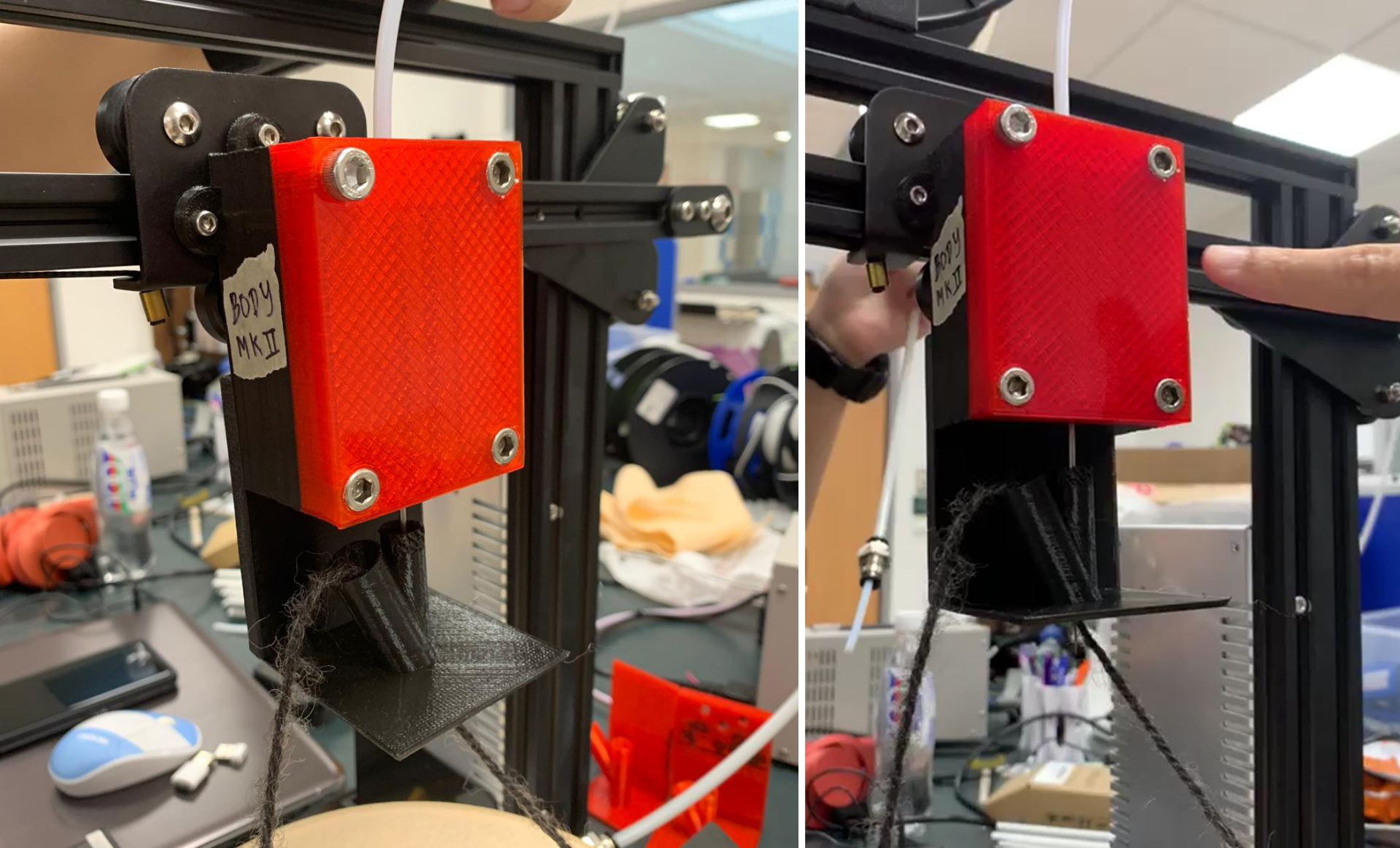
When roughly assembled, this is how our current prototype looks like. It’s not perfect, but it’s a start.
| The Good | The Bad |
|
|
Video of prototype of Main Body Mk II and Feeder Mk II. Observe that the needle is unable to poke out beyond the bottom of the Feeder base. 🙁
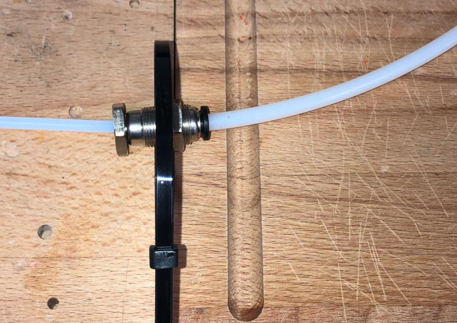
We considered using the same dimensions and re-printing the red body piece with black filament instead, but for now we decided to focus on building an MVP and smoothen out such kinks in July. Potential solutions to reduce friction would be to use PTFE Lube, or attach a PTFE tube in between the screws of the Connector Mk IV (see diagram below). One difficulty in achieving this is that most standard glues are not able to be used on the 3D printing plastic material. Another possibility is to re-print the Connector piece with countersinks so the screws would not protrude beyond the surface at all.

(Left) How the PTFE tube would be attached to reduce friction between the Connector and Main Body.
(Right) How we can secure a PTFE tube to the Connector piece.
… But for now, our focus will be to produce our MVP by June. So we’ll accept its current state as is and continue using the Main Body Mk II for prototyping purposes. 🙂

A lil’ extra look at Vanessa’s notes during the designing process!
Connector Mk V
To accommodate the spacing required for the needle and tubing down the centre of the piece, we opted to use smaller screws instead (or the screw bore would ‘merge’ with the outside!). We wanted to reduce friction, so we decided to add countersinks into the piece. Additionally, eight screws instead of six screws would guarantee a much tighter fit to keep the tubing in place. The needle was okay in previous versions due to the ‘hook’, but the tube had nothing really holding it in besides friction. Thus it depended on how tight the Connector pieces were joined together.

Connector Mk V, with all screws (sans one) in! It was already pretty secure.

How the Connector Mk V fit inside the Main Body Mk II.
Connector Mk VI
We wanted to make sure the Connector piece was even more secure and able to clamp the needle and tubing shut, so decided to have a mix of 4 smaller screws for the thinner needle and 2 larger screws for the tubing area. This was of course done with countersinks to further streamline the design. Compared to the previous five versions, this latest Connector Mk VI piece was able to clamp the tubing and needle together more tightly than before!

Connector Mk VI. Hopefully, this will be the last one.
Feeder Mk IV
Given the above criticisms for the assembled prototype, we needed to print out a modified Yarn & Needle Feeder. To account for the need for the needle guide tube to be shorter, we decided to move the entire piece upwards, closer to the Main Body. Here are Vanessa’s notes on this. (NOTE: The correct dimension on the right should be to move down by 10mm and not 12mm. Sorry for the typo while writing it down!)
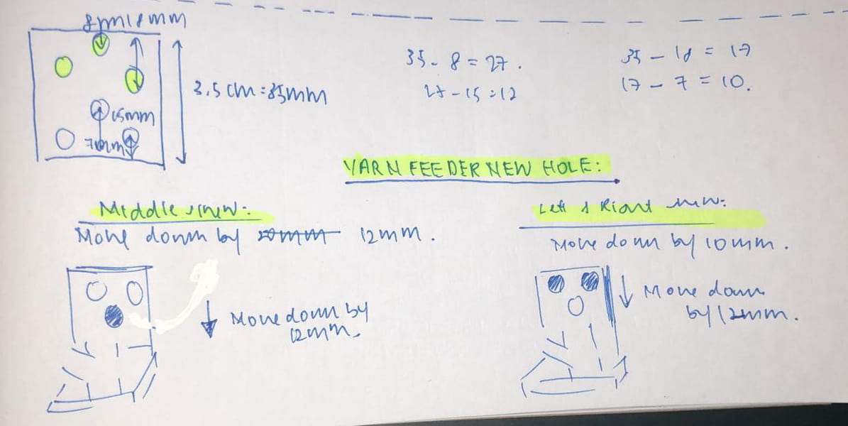
Vanessa’s notes!

Feeder Mk IV. Notice the imperfections 🙁
The needle and yarn guiding tubes were left as is in the printed model we sent for printing. Unfortunately, the final piece was printed with two issues:
- The backing of the Feeder Mk IV was too high up; it prevented the Feeder from fitting nicely onto the backing of the Main Body. This was the biggest issue.
- The opening of the needle guide tube was not printed correctly. However, despite its less than ideal printing appearance, it was still able to attach to the adaptor piece, so we are ignoring this for now and treating this piece as merely a prototype.
To solve the first issue, rather than wasting time and filament printing out the exact same model but with a shorter backing, Tony helped us to saw off the top part of our Feeder! Thank you so much, Tony, we owe you so much!!! 😭😭😭
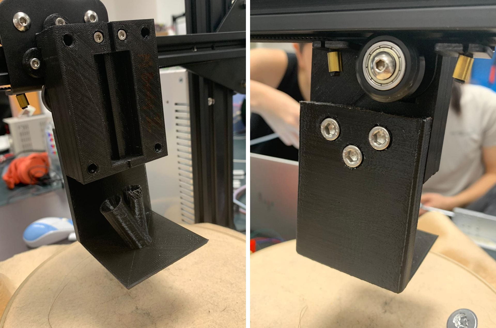
Feeder Mk IV, successfully attached to the Main Body Mk II (back). Observe the sawed-off top portion (right image) and the poorly-printed needle guide tube (left image).
First Full Assembled Prototype Test Run!
The moment of truth…!
Main Body Mk II, Connector Mk VI, Feeder Mk IV, all fully mounted onto the 3D Printer.
Video of how the assembled prototype works, replacing the LA’s linear motion with our own hand’s.
It works! The needle can be seen poking out beyond the base, by about 1-1.5 cm, which is ideal. Currently, the assembled prototype for the mobile stabbing needle piece works. It might not be perfect (see: The top left screw of the Main Body Mk II cover piece can’t be screwed in any further; sawed-off top portion of the Feeder Mk IV backing, and poorly-printed Feeder needle tube), but it works for our MVP.
… Just a few seconds after the above footage was captured, Alexis accidentally broke the needle. Sorry.
Stationary LA Piece
With the mobile stabbing needle prototype just about working, we may now move on to our next obstacle: how to get the LA working, including how to control its movement better, and how to mount it to the entire contraption.
Controlling the Linear Actuator
With luck hard work, we hope to be able to gain better control such that the x/y movement of the 3D printer would be able to coordinate well with the LA’s z movement. That is, we’ll be able to see the following motions played out:
- The printer is stationary.
- Needle stabs downwards continuously and stops.
- The printer then moves slightly to the next location and stops fully.
- Needle stabs downwards continuously and stops.
- … Continued.
This would be the most ideal movement, as our current fear is that if the printer moves while the needle is still embedded in the styrofoam, it would break due to its fragile nature.
Today, we hooked up our stepper motor, which was given by Tony from the M&T Lab to the LA piston, an open-sourced Ramps 1.4 controller that is connected to an Arduino Mega 2560 board, and a laptop. With the help of Qi Jie and Karn, we managed to control the LA movement better by either modifying the hardware or software itself.
| Hardware | Software |
|
|
For now, we will work with the modification to the hardware and get the needle movement to be extremely fast and the X/Y movement to be extremely slow. Hence, reducing the chances of getting the needle dragged along the fabric in our MVP. However, fret not, we will not give up in trying how to directly modify our stepper motor code obtained from the Marlin firmware to get it recognized and executed by our 3D printer during embroidering.
Linear Actuator Mount Planning
Issues we need to overcome:
- Must be secured very steadily as it vibrates a lot, especially at high speed
- Must allow for full movement of piston
- Bulky, heavy
We concluded we needed some kind of external frame, either attached to or separate from the 3D printer, that would be strong enough to ‘house’ and support the LA. A primitive solution would be to clamp the LA to the table, but a more elegant (albeit time-consuming) one involves printing out some 3D printed parts that can sufficiently attach the LA to the printer, for easier transportation.
Since our project progress is relatively good (Thanks Dr Ho for the Green/Orange rating 🌞), we decided to aim for the more elegant solution. Using some aluminium profiles lying around the M&T Lab, we did a mock-up of how the support frame would look like.

LA Mount, using aluminium profiles and empty hands. Including Tony’s.
The mount would be secured to the 3D Printer frame, with the LA inverted such that the piston is facing skywards. The stepper motor for the LA would be attached at the end of the LA closer to the ‘ground’. The external tubing (to transfer the LA’s motion to the needle in the Connector in the Main Body) would also be attached to this mount. We can 3D print a bracket or magnetic bracket that will be attached to the mount, and it would help secure the external tubing. The bracket will be attached parallel to the LA.
Mock-up of how we plan to clamp the external tube to the mount.
To move forward with this plan, we removed the DC motor from the LA. We need to obtain the piston structure, that is screwed onto the LA bracket. We can then ignore the bracket as we design and 3D print our own bracket that would be able to accomplish our needs above. This is especially needed because the stepper motor is of different size and shape from the DC motor and this needs to be accommodated for by the bracket. Finally, our new bracket is mounted onto the aluminium profile mount that is attached to the 3D Printer.
Until we get that sorted out, we’ll have to resort to the primitive solution 😂

Desperate times call for desperate measures… For now. Behold, how we’re keeping the LA in place until we get the actual mount designed and printed.
We ended off the day taking measurements for the bracket. It’s truly been a long day indeed, and we’ll have the weekend to rest up before continuing the following week. Good job team!!