When: 24 June 2019, 10am
Members Present: Claudia, Vanessa and Carissa (Happy birthday Alexis!)
Linear Actuator
LA Mount Mk I Part I
Claudia and Vanessa picked up from the previous meeting and started off by making more measurements to design the LA mount/bracket to fit our bigger stepper motor and the piston structure together. After a few prints on the 2D printer, we managed to get our dimensions right!!


Vanessa’s sketch for the concept and dimensions of the LA Mount
With the design all ready, we sent the LA mount/bracket for printing in the big Creality printer.
One problem we noticed while designing the bracket was that the hole to attach the stepper motor shaft to the linear actuator is too big for the shaft, making the connection loose and unstable. Some solutions we considered:
- Use masking tape to tape around the rod to increase surface area and hence diameter of the rod.
- 3D print a ring to fit into the hole and shaft and use the tightening screws on the linear actuator as a clamp.
After Carissa came, we tested out Option 2 with two different ring designs – one which accounts for tolerance and fit (+0.2mm for each measurement) and one which does not. After printing out both ring designs, we found that the thickness of the ring must be minimised for it to be able to fit both the shaft and the ring. However, it is not feasible to 3D print out such a thin ring using PLA filament. Instead, we have decided to focus on Option 1 (using masking tape) for our first prototype.

The motor shaft managed to fit into the hole with the help of a lil’ masking tape.
Preparing to Build the Aluminium Frame
While waiting for for our LA mount/bracket Mount/Bracket Mk I to print, we decided to work on the aluminium profile, where we would eventually attach our LA unit. While exploring our options, we studied Team Balance’s bracket. It allows two pieces of aluminium to be connected perpendicular to each other without needing to drill holes.

Inspiration from M&T Team Balance’s bracket.
We took inspiration from the design to design and 3D print our own Major Bracket Mk I (in grass neon(ish) green)!

Major Bracket Mk I.
It printed out well (though it took longer than expected), but the position of the holes were off-centre. Hence, we have to shift up the holes by about 6 mm and re-print our bracket again, which we will do so tomorrow.
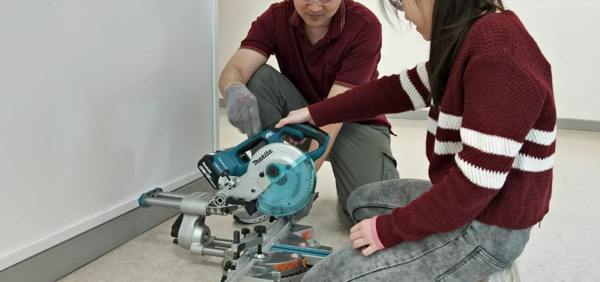
Other than the bracket, we also made some measurements for the lengths of aluminium profile required. We asked for Tony’s help to saw the aluminium pieces to the correct length. Thank you Tony!!!

Tony & Vanessa sawing the aluminium profiles in matching outfits.
LA Mount Mk I Part II
Everyone was checking their hall allocations in the M&T lab and amidst the chaos, Karn called us because our print of the LA mount was becoming crooked. 😣 Luckily he told us early, so we could stop the print and not waste too much filament (and time).
We seized the opportunity as a chance to check the dimensions of our LA mount design, and found that one hole did not align correctly with the holes on our motor. Other than that, everything went well, and the linear actuator works AMAZINGLY!! We suspect that the issue of misalignment might be caused by the printer, so we have sent our LA mount for printing again! Hopefully all will go well and we’ll be able to collect our LA mount tomorrow. ☺️

Linear Actuator Mount Mk I. Technically incompleted.
Manually moving the LA with our hands while it fits nicely in LA Mount Mk I.
Tomorrow, we aim to assemble our aluminium profile-LA structure and attach it to the 3D printer, and figure out the bracket/clamp for our external tube. Till we meet again!