Milestones
We have outlined our process and development into a few milestones for our team.
Milestone 1 Self-piloting DJI Tello
Milestone 2 Getting the Pixhawk to work
Milestone 3 Self-piloting Pixhawk
Milestone 4 Attach Release Mechanism
Milestone 5 Complete Flight tests of the two drones working
Timeline & Learning Experience
-
22 – 26 June: Meet up, Brainstorm, and Introduction
- We met up virtually for the first time to get to know one another such as knowing what are our strengths, style of communication and working preferences before embarking on the project.
- Hands-on with the DJI Tello drone. Look at what the lab has and familiarize ourselves with the drone.
- Consider drones that we can use. After doing our research and consulting Kanesh, we found the Pixhawk to be the most preferable for our project.
- Contact Kanesh to find out everything we need to know about the Pixhawk
- Source and Determine the materials needed (GPS, telemetry, Lidar Sensor etc) that can be used and compatible with Pixhawk.
- Design a release mechanism and how it communicates to the drone when it reaches the destination.
A few designs have been tossed around. We have a claw big claw mechanism, another with 2 claws to hold the package, a hook mechanism, and an electromagnet mechanism. After much deliberation, we decided to challenge ourselves to work on an electromagnet mechanism as that has not been widely seen or adopted. - Decide if we need to purchase a drone or if the lab has a working Pixhawk that we can adopt
- Purchase Materials for Release Mechanism: Neodymium Magnets
We had a virtual meet up to discuss the type of magnets we can use. We knew we would need a powerful magnet that is small and light enough to carry and transport packages. The size of the magnet matters because it cannot be too big that it is hard to install on the drone. Also, a magnet too heavy will be tough for the drone to fly. We concluded that neodymium magnets were very suitable given their size, weight, and force. As we need to also experiment the magnets used, we bought a few neodymium magnets of different sizes.
-
29 – 3 July: Working with the DJI Tello
- Work with Tello Drone, test the accuracy of the drone.
We familiarise ourselves with the DJI Tello drone. Test how sensitive it is and practice writing code with it. - Work on the release mechanism
We discuss and drew up a rough sketch to show how the electromagnet would work such as how much power we need, what is the source of power, etc. - Draw up an electrical circuit for the release mechanism
- Work with Tello Drone, test the accuracy of the drone.
-
6th – 9th July: Getting Pixhawk:
- Obtaining the Pixhawk from the lab, including the necessary parts.
- Getting Tello to fly on a planned path.
After weeks of trying, we managed to get the Tello to work. This concludes our first milestone. You can view our video on the Media page. - Test out GPS Accuracy of ardupilot
We assemble and reconfigure ardupilot. As we are new to Mission Planner, we played around with the software to get a better understanding. We initially could not get the ardupilot could not connect to the Mission Planner. After further configuration and troubleshooting, we managed to get it connected. The next step was to load the GPS properly. - Hands-on with Flight Simulation
- Working on the solenoid behind the release mechanism.
- Test electromagnet solenoid.
- Worked with an iron nail to make an electromagnet
- Concluded it needed more than 20 rounds of coil
- We realised that we may need to make a stronger magnet and we have to source the right materials for this. As such, we decided to consult Dr Ho or Kanesh to see if it would be better to purchase an electromagnet.
- After our first consultation presentation with Dr Ho, Tony, and Kanesh, we concluded confidently to purchase an electromagnet instead.
- Draw up a list of remaining items to purchase and send to Kanesh
- Kanesh was very helpful and told us which items were compatible with the pixhawk and which were not. After making the changes, we got approved of the list of items to purchase for our drone.
Experiments with makeshift solenoids
 Regarding the release mechanism, we conducted some tests to gain some understanding and grasp on the magnetic field strength of solenoids. We used made shift materials that we got from the lab and home. An iron nail of 99% pure iron with a diameter of 3mm was used as the solenoid core. Wires obtained from the M & T Lab were used as the coils. We drove a current of 1A with 5V through twenty coils of wire around the nail.
The magnetic field strength measured was then measured to be a meagre value of 0.06T using the tesla meter. Though this figure was low, we wanted to test if there was indeed repulsion if we were to face its pole to the like pole of a permanent magnet.
After identifying the poles of the magnet using a tesla meter, we put the like poles of the solenoid and the permanent magnet together and turned on the solenoid. The result was that the solenoid was still attracted to the permanent magnet although the like poles were facing each other. Despite this, when the like poles of the solenoid were facing each other, the attraction between them was weaker than when the unlike poles were facing each other. We concluded that the solenoid’s magnetic field was too weak and the permanent magnet’s magnetic field strength overwhelmed that of the solenoid. Hence the core of the solenoid remains attracted to the permanent magnet.
Because of this, we decided to use an electromagnet from the market instead of creating one.
Fixing the hardware of the GPS System
GPS snapped at the bottom
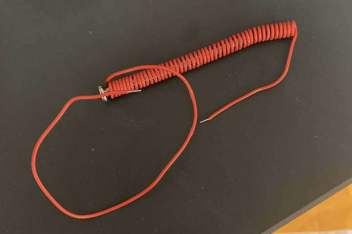
 The GPS module we’re using is the Here+ from Hex. Having our first hands-on on the GPS system, we tried to calibrate the GPS module with the Mission Planner software. Upon establishing a connection with the computer, we found that the GPS frequently lost connection. Tinkering with the GPS module, we realised that because the cable was flimsy and the wires had snapped at the base from excessive use during past projects, the connection to the computer was inconsistent. So we proceeded to solder the wires at the broken points. The challenge was with the thin wires, snipping the plastic cover away from the wires. This took a couple of hours.
-
13th – 17th July: Assemble Pixhawk, Radio Transmission, and Lots of Soldering.
- Assemble and Test Pixhawk
- Rewire and assemble the drone
- Dissemble the pixhawk, remove the wires, carefully, and We managed to power on the telemetry to communicate to pixhawk remotely
- Ensure drone’s CG is good
- Test and calibrate GPS
- Hands-on with Flight SimulationWe also played around with the neodymium magnets. Finding the right size and weight, and force was tricky. Some of it was too strong. It may affect the GPS signal when we do assemble the drone. We considered putting an electromagnet shield, or build a model to put on the drone using 3D printer, such that the GPS is further away from the magnets. However, this may affect the CG of the drone. We will work on this further when the time comes.
- Ground radio transmission
We tried to power it on and get it to work. It is still showing “switch error” on the display.
Through research, we realised that one of the switches is missing from the controller. We opened it up and found the wire has broken off from the switch, and the nut supporting the switch is missing.

-
- We solder the wire to the switch.
Now it’s working! We found a nut to hold the switch and fix it to the controller.
- We solder the wire to the switch.


-
- Started calibrating GPS.
-
- Release Mechanism
- Plot out 3D schematics of the release mechanism
-
- Measure the magnetic field of neodymium magnet
The release mechanism works by using an electromagnet to repel the other magnet, hence forming a release of the item. However, after testing out with an electromagnet, we realised there are complications that were beyond anticipation. It seems like it was possible for the electromagnet to not be able to repel the permanent magnet due to the unbalanced magnetic force. The electromagnetic needs to cancel out the force of attraction from the permanent magnetic in order for the release mechanism to work. Currently, the permanent magnetic is too powerful even with 25N. It seems like the permanent magnet is still attracted to the electro rod inside the core. Hence, this makes things challenging.
- Measure the magnetic field of neodymium magnet
-
- Make purchases of remaining items
Checked with Kanesh and made the purchase of items necessary for building the drone, and the release mechanism. With covid19, there were delays in delivery. As we aim to finish the project by August, we decided to pay for the express shipping so that we can progress on our project as quickly as possible. Thankfully we managed to receive our items at the end of the week.
- Make purchases of remaining items
Testing and calibration of GPS
Having the hardware of the GPS fixed, we proceeded to calibrate the GPS with the mission planner software. The set process of calibration took about 30mins. Initially, the accuracy of the GPS was way off. The drifting coordinates were a maximum of about 200m from the actual coordinates. We then decided to switch from GPS to China’s Beidou system and increase the number of satellites used to triangulate our location to 14. This drastically improved the accuracy of our set-up and we deemed the inaccuracy problem of the GPS system solved.
Electromagnet – permanent magnet attraction weight testing
With the arrival of the electromagnets we bought online, we proceeded to test if the attraction between its core when it’s off and the neodymium magnets we used are able to support more than 100g of weight. We had to do these testing in order to determine which neodymium magnet to use as the permanent magnet in our mechanism. A magnet too strong would overwhelm the magnetic field of the active solenoid and not detach from the electromagnet. A magnet too weak would detach easily from the electromagnet but would face challenges carrying the payload. 
The apparatus used for this experiment was a small weighing scale, the magnets and some tapes.
- Measured the total mass of the electromagnets and the neodymium magnet used.
- Determine the weight of the weighing scale by suspending it by holding it by its holding dish. The reading of the scale will be negative, but its weight will be the same magnitude in positive. The weight was measured to be 181g.
- Tape the neodymium magnet to the scale.
- Hold the whole set up from the electromagnet. If the set-up holds, the attractive force is able to hold more than 181g of payload.
Both type of magnets, the rectangle and button ones were able to support more than 181g. We wanted to actually find the maximum weight these magnets can carry but since our payload is only meant to be 100g, we stopped here.
Repairing the transmitter
When we first switched on the remote controller, Its cautioning alarm blared and its display showed the message “switch error”. Not knowing what this meant, we fiddled around with it for a while. After some research about the controller model online and some inspection, we realised that one of the switches is missing from the controller. We opened it up and found the wire has broken off from the switch, and the nut supporting the switch is missing. because of this, the switch knob dropped into the controller’s housing.
We then fixed the non-functioning knob’s wiring with soldering. We found a new nut and used it to fasten the knob to the controller.
A requirement for modification to the release mechanism’s circuit


While experimenting with the electromagnet and neodymium magnet’s attraction strength, we discovered that the preliminary circuit plans of the release mechanism would not work. As seen in the preliminary circuit sketch on the right, the Arduino nano is connected in series to the electromagnet. After setting up a circuit using a computer as a power source of 5V, and the Arduino nano as a switched arranged in series with the electromagnet, the magnetic field strength of the electromagnet measured was really weak. After some inspection, we found that the maximum permitted current of the Arduino nano was only a meager value of 50mA. Hence we decided that the preliminary circuit design will not work. We brainstormed a rough idea of using a transistor as a switch instead of the Arduino nano. The Arduino nano would be arranged in parallel to the electromagnet. During activation, it will apply the activating potential difference across the transistor, allowing the transistor to be forward-biased in one direction. Hence permitting current of sufficient magnitude to power the electromagnet.
Testing of electromagnet-permanent magnet repulsion
 Using the current generator in the M & T lab, we send a current of 1A and 5V into the electromagnet. We found that when the magnet is in direct contact with the electromagnet, they can’t repel each other. This may probably be due to the strength of the permanent magnet and the shape of the solenoid’s core. We found that only at a certain distance, the two magnets can repel. Put them too close and both magnets won’t. They’ll stay attracted. Put them too far and they can repel but might not be able to support the payload’s weight when the electromagnet is off. Hence we set off to find this optimal distance between the two magnets.
20th – 25th July: Assembly of the drone, transmitter Issues!
-
Drone
-
Calibration of sensors
-
Tweaking of parameters
-
Refinement
-
-
-
Release Mechanism
-
3D print release mechanism separator
-
Soldier and create a circuit board for the mechanism
-
Assemble release mechanism and test it
-
We got the magnet to work. It lifted 100g of load! We designed a separator to hold the electromagnet and magnet in place and included a gap between the two magnets. this helps to reduce the strength of the magnet.
-
- Was tasked to do another release Mechanism – using a trap door.
- troubleshoot the Arduino, where the Arduino nano could no load the program that we coded. After some time, we realized the one we used was a “fake” version.
- We seek help from Kanesh after trying to connect the radio to the receiver for a few weeks. Our radio had a “phantom” press as we could not press what we want on the controller. Finally, we could connect the radio by replacing a new one.
-
Release Mechanism
In our previous testings of the electromagnet, we found the optimal distance between the electromagnet and the magnet to be 5mm.
 Hence, we designed a separator as seen on the right. This separator will be attached to the electromagnet. We only managed to find the optimal separation of 5mm after 3D printing many iterations of separators with different separation widths. When the box and the drone are connected, the permanent magnet will be
 situated at the bottom grove. This separator ensures that the magnet and permanent magnet are 5mm apart at closest. After having the separator and the optimal separation distance, we decided to use two pairs of electromagnets and a permanent magnet to hold the box. This allows higher stability when the box is held from two points. This system worked well.
Release Mechanism circuit
Having revised the mechanism circuit, we sought to use a transistor to be the switch of the electromagnets so that the Arduino nano does not need to be arranged in series to the electromagnet due to reasons explained in the earlier sections. However, we encountered another problem. The code that was coded to run the mechanism circuit would not run on the Arduino. After much recording and testing, we found out from Dr Ho that the Arduino nano we were using was a counterfeit and hence can’t run the code we codded.
Decision to revise the release mechanism design
Having a progress meeting with Dr Ho, we received some feedback that made us decide to change the fundamental concepts of our release mechanism. Our current release mechanism that utilises magnets require the loss of two magnets whenever the payload is delivered. This is because when the goods are released, it is released along with the box and the two magnets attached to it. This proves rather wasteful. Hence Dr Ho and Kanesh suggested we design something that relies on trap doors that would release only the goods.
Reception of new transmitter
After days of fixing multiple issues with the transmitter, we hit a brick wall. The transmitter has a phantom press whenever it turned on. This key remains activated throughout the use of the transmitter, a perpetual blaring of feedback takes place whenever it’s on. After bringing this issue up to Kanesh, we received a new transmitter from him.
26th – 30th July: Minor Breakthrough then a setback
-
- We sought a power module that connects to the Pixhawk2 from Kanesh. Thankfully, he had one extra and we went to his lab at one-north. Without the power module, we could not test and calibrate the drone.
- we had to learn how to use and connect the power module as we were not sure if the power module I/O could connect to the battery supply.
- Once we managed to connect the power module to the power supply, we were on our way to calibrate the controller to the drone. We troubleshot the controller to the drone for a few hours.

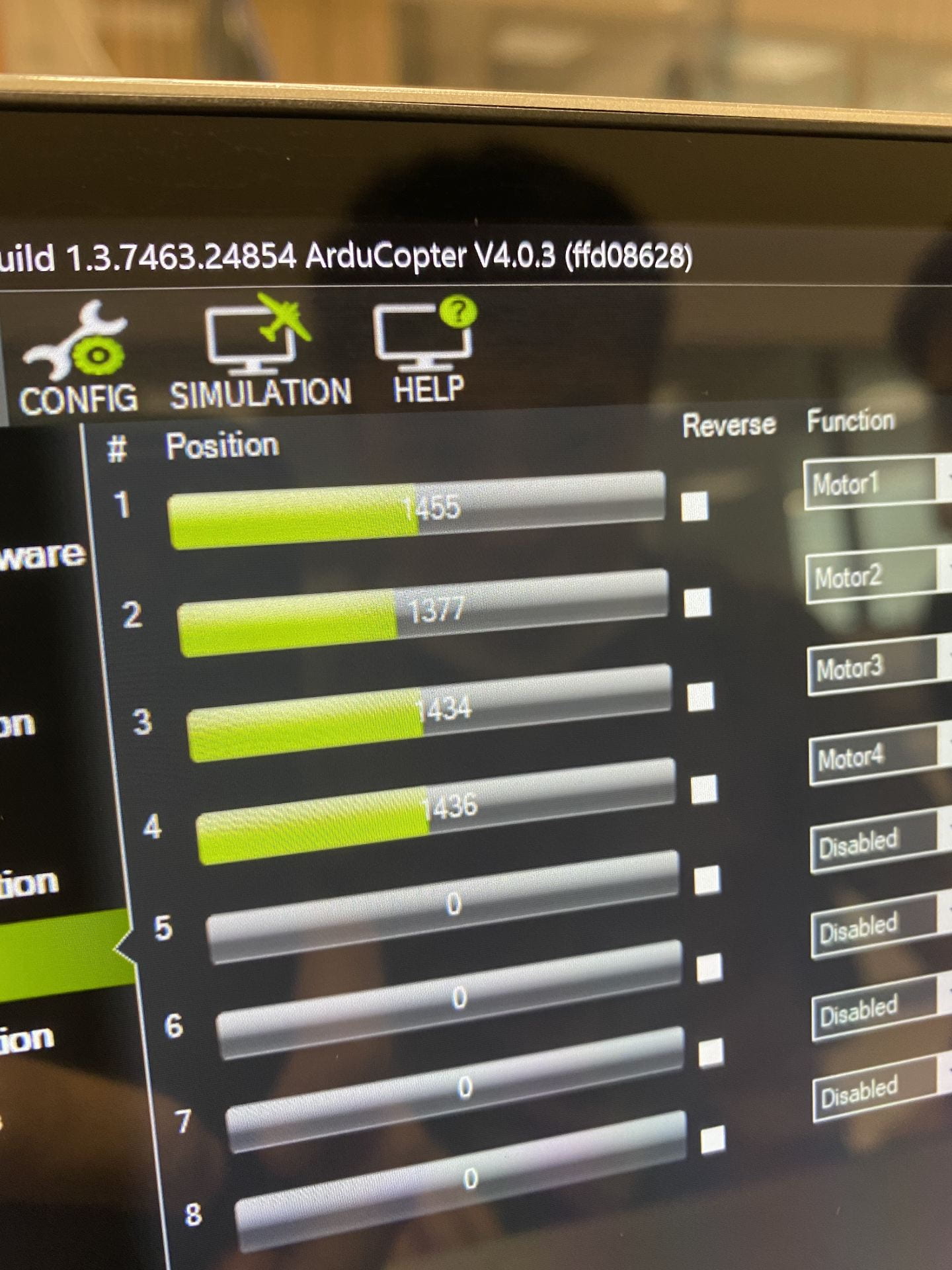
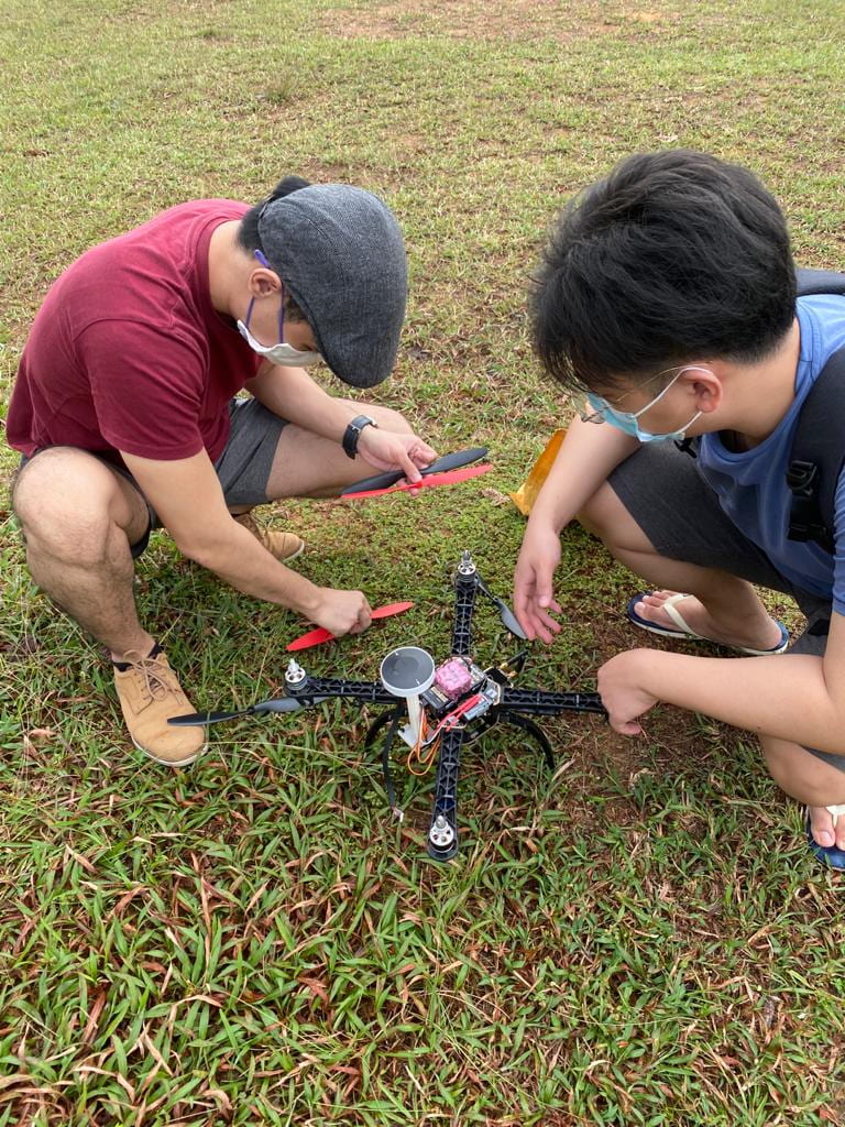
- We did the necessary checks such as to calibrate GPS, compass, ESC, and the stability of the frame itself. At last, we successfully connected the drone to the pixhawk. We test the motors to make sure that we attached the right blade. This was tricky because we do not have experience in this. We googled information online to ensure our blades are in the right direction with the motors.
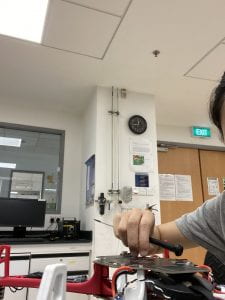
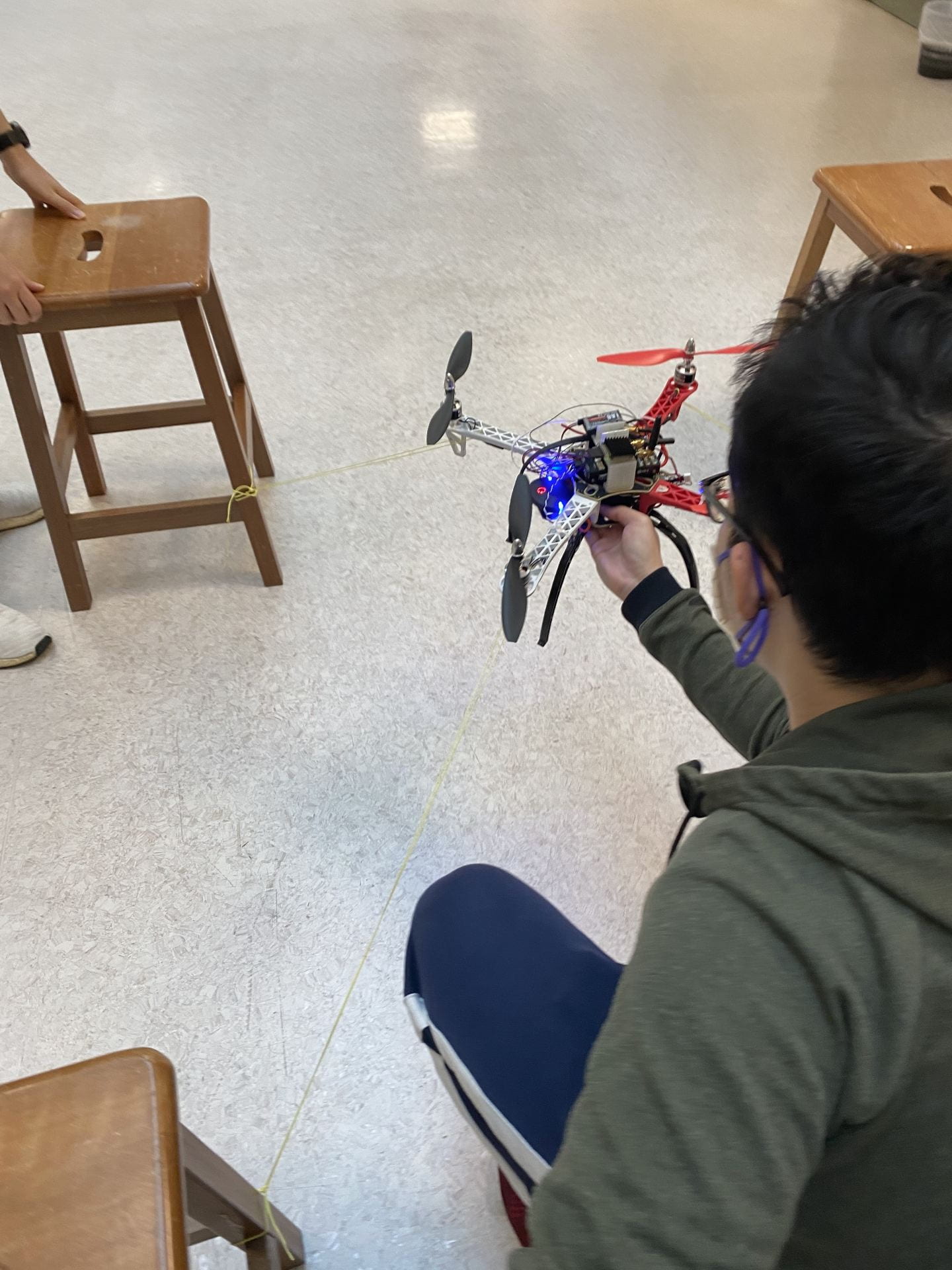
- Our first breakthrough occurred when we were ready to do a flight test to see which direction the blade would turn and how stable the drone is. We did a mini “test-flight” under supervision. A string was tied to each leg of the drone to a 4-legged chair. This is so that the drone cannot fly higher or away from the current location.


- During the flight test, the drone leaned towards one side. We sought to figure that out by recalibrating the ESC and IMU again. Tested the servo output of the motors to check if the motors were moving at the same speed and in sync. We removed the blades during the tests. Reset the entire drone. Decided to take out the legs of the drone as they were damaged by the previous user which could be the reason why the drone was lopsided. After eliminating the legs, we tested the drone again and found out that motor 2 was problematic. It was spinning slower than the other motors. We changed out the motor with a spare motor that we had. We encountered a minor setback when we replaced the motor as the ESC attached to the motor burned out. The wires from the ESC were touching each other. We immediately disconnected the drone and plugged out the power supply.


- As such, we had to seek a new body for the drone. We reassembled the drone one the DJI frame. We struggled again as we could not connect the ESC to the controller. The transmitter was not picking up any signal from the ESC.


New Release Mechanism Design


This week we also embarked on a new release mechanism for the drone. We experimented using a servo and trap doors to build another release mechanism. We tested and drew out housing for the box where the items can be transmitted. This took careful considerations of where to place the servo, how the trap door should word, and how will the box be attached to the drone. The image on the left above shows the box of the trapdoor “cage”. A hole shaped according to the groves of the servomotor was made in the side to fixate the motor. To ensure a good fit, we printed a few of these test holes to attain the best hole diameter. One of these test units is shown on the picture on the right side above.

To facilitate easier loading of goods into the box, we designed a secondary door behind. This door comprises of a simple sliding slab with a simple locking mechanism to keep it closed during flight. This secondary door allows us to load goods in without electrically turning on the trapdoor at the bottom.
- 3rd Aug – 7th Aug: Good News: It works!
- As the ESC short circuit, we have to seek new items for the drone. We found a drone shop in Lavendar called Rotor Hobby after searching on Carousell App since we could not find local sellers on google, and other online market had delivery delays. This caused a lot of worries and added stress for our group as we were almost back to square one. Also, we were warry of our deadline and budget.
- We got 4 new ESCs for the quadcopter, a packet of heat sleeves, and pins to connect the ESC to the power module. We were hoping that the damage was only in the ESC and not the pixhawk. Otherwise, we have to make a trip back down to RotorHobby and purchase more stuff. We fixed one of the ESC first, instead of installing all 4 ESC to the drone, pair it and see if it works. Good News: It works! A huge lift of our shoulders when the ESC worked! (we celebrated by eating doughnuts).


- This week we advanced further with our new release mechanism.
- Purchase more items that we need for the drone at Rotor Hobby (our new best friend – although the store is pretty far away. This took up a lot of time)
- We sourced and prepared a list of items that we need for our second drone on a spreadsheet – included the reason for purchase, source, and quantity).
- We could not use the current DJI Motors that were on the DJI frame as we were missing the Counter Clockwise nuts. We even went back to our best friend, Rotorhobby, to look for the nuts but to no avail. It was a wasted trip and time. As such, we swapped back the previous motors to the DJI Black Frame and connected with the new ESC.
- We started calibrating the controller. With the help and supervision of Kanesh, he notified us that there is a lag in the controller and the drone. We had to research and recalibrate the PID. After some research, we managed to change to a PID that is suitable for the purpose of our drone.
- The new PID setting we had is:
- With a new PID, we were able to finally test flight again! This time the flight test would be outdoors. This test flight could tell us if our drone is working well and if things are well-balanced.
- The drone took off while being controlled by the flight controller. This test went rather well. It could land and take off rather properly we showed signs that the drone is “alive and well”. Everything is on track. Our next step would be to fly the drone autonomously.


- 11th – 14th August – The work continues.
- Once we managed to test the flight test with the controller. We were ready to test the autopilot. Keeping safety at the top of our priority. the things that we took note of include:
- our controller could take over the drone in case of any mishaps while the drone is flying autonomously. We made sure this was working when we successfully calibrated the controller. There are 3 modes (one flight controlled by the remote, one is to let the drone fly autonomously, and another is for the drone to fly back to the original position.)
- We went to the basketball court where the old Hall 7 was, just in front of SPMS, to do the flight test. This basketball court is below the hill. So there were trees around the edge of the basketball court that could prevent the drone from flying away and being a physical hazard. Since it was at the basketball court below the hill, there was nobody there. It’s inaccessibility meant that there is low traffic (actually nobody goes there).
- We tied a string on the bottom side of the body for safety purposes.
- For our first autonomous flight test, we set a flight path through Mission Planner where the drone to fly up vertically 3m and land on the same spot. During the test, Kanesh told us what to do in case the drone flew towards us. Although we were spread out and standing a considerable distance away from the drone, Kanesh warned us to “be prepared to run” at any time during the test in case the drone were to fly at a fast speed towards us.
- Once we managed to test the flight test with the controller. We were ready to test the autopilot. Keeping safety at the top of our priority. the things that we took note of include:


-
- As we conducted the flight test, the drone did not fly according to the flight path. It kept drifting away horizontally from the current position. We figured that it was because of the lack of GPS signal as there were not as many satellites the drone was connected to that day. This could also be due to the cloudy weather. Check out the video below. The drone kept drifting from its current position.
- As such we researched and will try experimenting to use Trim to minimise drift and see if we can enhance the GPS signal either through calibration or attaching another GPS module.
- We went to research and drew up a list of items, and made sure it was within the budget, to purchase for the second part of our project – the second drone – to Dr Ho.
- during the connection of the pixhawk to the raspberry pi, there was a connection error. This took up a lot of time to solve because the problem did not lie within the code but the connection of the wires instead.
- The online picture that showed the pin layout for the pixhawk 2.1 was misleading. It connected the RX to RX and TX to TX when it should be RX to TX, respectively. This is also probably why the Lidar did not work.
- As we conducted the flight test, the drone did not fly according to the flight path. It kept drifting away horizontally from the current position. We figured that it was because of the lack of GPS signal as there were not as many satellites the drone was connected to that day. This could also be due to the cloudy weather. Check out the video below. The drone kept drifting from its current position.
3rd Redesign of the Release mechanism:
During the presentation on the 6th of August, we got valuable feedback for our release mechanism.
Our current mechanism encompasses a trapdoor design with the door’s axel directly connected to the motor. With the rotation of the motor, the door rotates down too. The problem with this design is that it makes the motor bear the weight of the goods inside the cage when the goods rest upon the trap door. The motor and the door can hence be turned if sufficient weight were to be rested upon it. The micro servo motor we use was not meant to bear weight. Hence, we proceeded to redesign our release mechanism, one that does not make the servo motor bear weight.
New design:

In the new design, the motor’s axel is rotated to be fitted vertically in the mechanism. It is now connected to a certain ledge that it will rotate. This ledge holds the door in place and is rotated by the servo motor. When it rotates out of position, the door is allowed to drop, hence releasing the contents in the cage. This new design makes the content’s weight dependent on the ledge which then depends on axel of the motor rather than on the gears of the motor. This design is overall more stable. The drawback of this design is that it has to be manually closed once opened. In the situation of delivery, once the goods are delivered, the door will be left open and hanging while the drone makes its way back to its post.

We have also made changes to the auxiliary sliding door at the side. The previous design relied on a separate component, the “tuning fork” to hold the door in place. A weakness of this design is that this small component can be easily lost. The new design relies on magnetism to keep the door shut. One magnet will be attached to the door while the other attached to the cage.
18th – 23rd August – Achievement unlocked! 3rd milestone achieved!
Test Flight
This was the 2nd week of school for us. Majority of our progress took place on the weekend where we went to test our drone’s flight at a popular drone flying area: a field at Old Holand Road.

Some problems we faced were that the initial logs and settings in the Pixhawk with the Mission Planner software were overridden accidentally. This took up a lot of time on the field to recalibrate and reconnect the drone. We were outside with no access to electricity, there was a pressure to complete all the necessary adjustments quickly since our laptop was running out of battery. But we eventually overcame this problem by redoing the calibrations and settings again.
The autonomous test flight was a success and below is a video that we recorded. This was done with a manual takeoff. The Ardupilot took over after the drone was in the air.
The drone was programmed to fly 75 meters into a coordinate in the field at an altitude of 5m and then land at the designated coordinate keyed into the mission planner. It was raining that day, so we rushed to complete the flight test under the rain.

24th – 28th August
Drone
Release Mechanism test
Having 3D printed the release mechanism, we set out to carry out testings on it. The servo motor that opens the door will be controlled by a Raspberry Pi. We wrote a code that was able to control the speed of the motor’s rotation. The code controls the angular velocity of the motor by turning a number of “steps” per second. This number of steps were variables that can be decided. The direction of rotation was able to be controlled as well. This only showed how the door could open. But we thought more seriously about how this would work in real instances, and we decided to redesign it to allow the doors to open and close.
We forgot to bring a crucial component; the small ledge that’s controlled by the motor and supports the trapdoor. We used a makeshift ledge made out of a biscuit cardboard paper packaging. Because the was no load involved in this testing, the makeshift ledge sufficed in supporting the trapdoor’s weight. From out testings, we proved that conceptually, the mechanism works. we now need only to test it with a 100g of weight and with the actual ledge component to ensure this mechanism can serve its intended purpose.
31 Aug – 4 Sep
We programmed the release mechanism to work with the servo motor. This is for the Delivery Box. We used the Raspberry Pi to send the signals. We have a lot of tests that week so we only managed to this much.
4th Release Mechanism Design:

Having gotten feedback from Kanesh again, we were spurred to come up with a mechanism that is able to close the trap door after delivery. This is so that the door will not be left hanging when it returns to its station. This iteration of the design consists of switching the trapdoor’s axel to the same side of the box as the motor. This is so that when the motor turns the ledge it is able to push the trapdoor up and hence close the mechanism.
7th Sep – 11 Sep
We started working on Precise Landing. We bought the RPI because we needed it to work with the release mechanism and also work on the precise landing that Kanesh advice us to do.
We took on the challenge and begin with the calibration of the camera.
The Pi camera needs to be calibrated due to distortion such as radial distortion. We found a function within the OpenCV library that does it.
- We installed opencv, since OpenCV need a lot of dependency, we need to sudo apt-get or pip install all those and compile it into an installer ourselves
- Installed the latest version of OpenCV (4.3), this process takes around 2 hours as compiling take an hour by itself
- Then, a checkerboard is needed for camera calibration
The colourful lines on the picture is OpenCV trying to recognize the location of each box
- Input the checkerboard and dimension and wait for 3 mins for opencv to calculate the error
- The error I got is low, 1% or thereabout
We adjusted the perimeters to calibrate the image captured by the camera. This took many days of consistent hard work before we managed to calibration successfully.
After calibration, we loaded the calibrated data into opencv and run aruco algorithm.
- This algorithm will detect the 3D location of the aruco marker. However, since the camera angle and then image angle is opposite of each other, a correction is needed
- The arucomarker can correctly detect the distance from the camera, X and Y coordinate as shown in the photo below
We used the dronekit (the library used to connect the raspberry Pi) that can control the Drone.
- For drone control using rpi, a few libraries is needed. (python3-dev python3-opencv python3-wxgtk4.0 python3-pip python3-matplotlib python3-lxml python3-pygame)
- After which I choose to use dronekit as it offers capability that is not present in other control algo
- To connect to the pi, TX need to plug into RX and RX to TX. Then run a connect algo
- The buad rate is set to 921600 for fast data transfer and serial port 0 is used.
- There are few setting in mission that need to be change as well, namely
- SERIAL2_PROTOCOL = 2 (the default) to enable MAVLink 2 on the serial port.
- SERIAL2_BAUD = 921 so the flight controller can communicate with the RPi at 921600 baud.
- LOG_BACKEND_TYPE = 3 if you are using APSync to stream the dataflash log files to the RPi
With the dronekit, we can override the signal sent to the RC controller, so as to control the drone.
Assembly of 2nd Drone:
We met up on the 9th September afternoon with what little we could make available from our busy schedules to start work on the second drone. We mainly worked on assembling the mainframes and attaching the ESCs to the frame.

We achieved the following below:
- Attaching the two platform to the frames of the drone
- Attaching the landing gears to the drone.
- Soldering the ESC wires to the integrated circuit in the platform of the drone.
We attempted to mount the motors on the drone too but discovered that one of them was burnt. Hence we only had 3 working motors. Not wanting to waste more time on delivery, Yuhan went to Sim lim square on a weekend to purchase a set of 4 identical motors.
14 Sep – 18 sep
We realised we needed more materials for the second drone. We needed to buy more motors and spare blade. We could not afford to wait for shipping as we needed to work on it quickly due to the deadline we have placed for ourselves to complete this as the semester has begun. It was even more difficult to find a time to work together, as teamwork is absolutely necessary to solve the problems and the drone can a lot of components that need many things to work together, and we all had schedules that clashed. Unfortunately, this led to the difficulties within the team, as we had to split up the work. We were doing our work separately and this did not help our group to progress together, even though we were advancing on the drones. This carried on for the following weeks as we approached week 7 (the crucial weeks where tests, assignments, and projects are due).
21 Sep – 25 Sep
We were focused on our midterms this week. We discussed on how to work the Second Drone as the parts to be fixed on the second drone is different. We struggled a lot to fix the new parts on the drone as the parts we found that was available were different from the one used in the first drone. There were issues with the wires on the receiver and the ESC. The new receiver was using different pins, so this could not connect to the pixhawk. To remap the wires to compatible pins, we have to figure out which of the aspect of the controller were the wires controlling. The ESC was short of one wire which made it hard to connect to the motors. These took up an immense amount of time and the work is carried on to the following week.
28 Sep – 2 Oct
Continuing the assembly of the 2nd drone:
Connecting the transmitter to the drone.

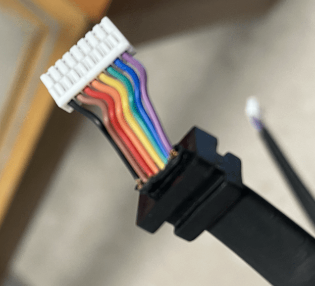
This second drone uses a receiver that requires an encoder between it and the Pixhawk controller. Hence, we needed to figure out the appropriate channels of the receiver and their corresponding input channels on the encoder. This was a very tedious process. We had to find out which channel on the receiver was working and which 3-dimensional movements together with throttle they correspond to. Fiddling through the wires, we employed trial and error and tested every channel. These results were documented in the notes above.

Because we were using multiple wire extensions as some wires were too short, we decided to soldier multiple wires that connect a single channel to input into one wire. This is to neaten things up and reduce confusion, as some of the wires used in series to each other were of different colors.
We then proceeded to work on the software aspect of the drone. Calibrated the compass of the drone, activated and configured the GPS system, and various other things such as ensuring each motor turn in the correct direction through appropriately swapping the wires that connected them to the ESC.
What was left was to set a connection to configure the PID and to configure the 3 transmitter modes of Autopilot, manual control, and return to home.
Testing of 4th Release Mechanism:
The 4th release mechanism was designed to be able to have its trap door closed after the goods have been dispenced. Up till now, it has only been a theoretical design. Hence today we sought to test it out physically. We initially wanted to controll it with a raspberry pi because we are using it when we integrate everything together. However, we did not have a raspberry pi today. Hence we used an Arduino nano. From the video above, we achieved limited success. The door was able to open and close. The next step is to test if this mechanism can support 100g and also be controlled by a raspberry pi with the same success.
Connecting the Second Drone to the computer and RC
We have assembled the second drone and now we face a slew of other problems where we had to connect the RC to the Drone and do the necessary calibrations such as ESC, Compass, and GPS calibrations, for the drone to take off. On top of that, we had to make sure that the motors were spinning correctly (opposite sides of the motor have to be spinning in the same direction).
2nd Oct
Configuring the transmitter
The biggest hurdle we face in setting up the drone on 2/10/2020 was to appropriately configure the three-channel switch to the three modes; Autopilot, manual control and return to home. This is for safety reasons. If the autopilot were to malfunction during flight, we are able to switch the drone mode to either manual or return to home, allowing us to get the drone safely back. To configure this, we, together with Kanesh watched some youtube videos and deconstructed them to learn how to do the configuration. After about 2 hours, we managed to successfully configure the three modes on the transmitter.
Testing of the release mechanism
Previously, we controlled the mechanism with the Arduino nano. Today, we tried to control the mechanism using the Raspberry pi. However, we found that when using the raspberry pi, the motor was not able to exert the same turning force as compared to when we used the Arduino. We tried to troubleshoot the issue with this. One of the source of the issue we suspected was that there was not enough friction between the hole of the turning arm and the gear of the motor. Causes the surface between the inner side of the hole and the gear to slide. Hence, the motor isn’t able to exert the required torque to close the door.
5 Oct – 9 Oct
This week, many of us had midterms. Hence we paused our work to focus on our revision.
12 Oct – 16 Oct
12 Oct 2020
We started off today by testing out the release mechanism. The release mechanism was controlled using both the raspberry pi and the Arduino. Using the Arduino, we managed to open and close the mechanism. However, using the raspberry pi, the motor turned too weak to close the trap door after making the delivery. We discovered that the cause of this was that the Arduino was able to exert 5V of potential across the circuit while the Raspberry pi can only provide 3V.
Hence, to solve this issue, we decided to use the battery in the drone to exert the required 5V of potential. The Raspberry pi, instead of being the main power source to turn the motor, will be connected to the gate of the transistor and serve as the switch to turn on the 5V potential from the battery.
Much of the time spent is in finding the appropriate transistor. The most common resistor used for this is the 222 resistors. However, the M & T lab does not supply this resistor. Hence, we were looking for an alternative.
13th Oct 2020

Today, after much pondering about the release mechanism, we suspect that it might be a coding problem. We resorted to using a larger servo motor to exert the required torque. To test this, we sawed a larger hole into the current release mechanism to accommodate the larger motor. To fixate the arm more firmly to the motor, we decided to nail the arm to the arm of the servo motor.
15th Oct 2020
Designing of Pixhawk and Raspberry Pi Holder. Today, we try to design a holder to put Pixhawk and Raspberry Pi. The holder is designed using Fusion 360. It consisted of 3 parts; the bottom is for placing Pixhawk. The hole in the centre is for ventilation and cooling of the raspberry pi. The middle shelf is for Pixhawk which will be secure in place with a screw at the front after placing the Pixhawk inside. The top will be a holder for GPS. The purpose of having GPS at the top is to improve the accuracy of GPS as GPS signals can be easily blocked.

19 to 23rd Oct 2020
Today I try to implement Aruco Detection onto the drone and using RC override to control the drone to land on top of a landing pad pasted with the ArUco Code shown below. The OpenCV library can detect the Aruco Marker in a 3D space once the marker size is known to the algorithm. The drone control was done using RC overwrite where the raspberry pi will send the RC signal to the Pixhawk to execute, while the Pixhawk is under RC overwrite, no human input will be processed.

At the end of this period, I was able to get the drone to detect the Aruco Code in 3D coordinate. The accuracy for height detection is only off by 2% which is decent for initial implementation. Once the drone detects the marker, it will move to hover above the marker and try to alight it before landing on top of it.

2nd Nov 2020
Since the last design of Pixhawk and Raspberry Pi holder. Some testing was done indoors and it was found that the previous design, although resistant to damages from falling, is too heavy for the drone to fly with. Heavy parts at the top of the drone will cause the Center of Gravity to shift upward therefore contributing to instability. Thus, a new design is envisioned. The new design consists of 2 parts, the Raspberry Pi holder and the Pixhawk holder. They are connected using 4 long M3 Screw as shown below:

Pixhawk Holder

Raspberry Pi Holder
The bump on the Raspberry Pi holder is for the screw to be screw in.
While assembling the holder, I found the hold to be too big. Therefore, I placed some hot glue into the hole to secure the screw. This has a surprising benefit as the hot glue act as a shock absorbent agent between the drone and the flight controller. It helps to dampen the vibration caused by the drone motor and prevent the vibration from interfering with the accelerometer build into the flight controller.
The front of the raspberry pi holder is for securing the raspberry pi camera used in precision landing, as well as telemetry used for communication purposes.
The GPS holder is hot glue on top of the Pixhawk holder as 3D print it as one single piece is proven to be quite difficult.

This is what the drone looks like after assembly.
10th Nov 2020
Today I performed an indoor flight of the drone. There are some stability issues with the drone caused by the shifting battery. Therefore, the battery was secured onto the bottom rack of the drone using some double-sided taps.
The method used to secure the Pixhawk-Raspberry Pi holder is proven to be less than ideal. As a result of a fall from 1 meter, the hold came loose from the drone. Therefore, a new rack was printed with 2 extra holes. Those 2 holes are used to secure the Pixhawk-Raspberry Pi holder to the drone using a cable tie to ensure a semi-permanent attachment.
EXAM PERIOD – Study Week
3rd Dec 2020
Today Indoor flight was tested again. This time around, the drone take-off without any stability issue as the centre of gravity is lowered with the removal of the landing gear. However, the drone cannot hold its altitude. I suspect there might be an issue with the lidar setting as the lidar is the main device used in altitude detection.
To test the issue with altitude holding, I tie the drone to the ceiling and perform the manual flight. After observing the flight data recorded by the Pixhawk, it is determined that the flow sensor was mistakenly used instead of lidar therefore rangefinder was not used as the primary height detection device. After changing the setting, the drone behaved normally. The final adjustment of PID was made to ensure throttle response to be ideal for takeoff and landing.
Also, I found out the RC overwrite is not the best way to control the drone to land on top of the marker as there is a 2-second delay from when RC overwrite was remove to manual control signal can be processed by the Pixhawk. During these 2 seconds, the drone will not react to any human input which could be dangerous. Thus, a new method of drone control was used. This mode is known as GUIDED_NOGPS. Under this mode, the Pixhawk will react to attitude control issued by Pixhawk but once the flight mode changes out of Guided, manual control can be immediately issued. This will remove the 2-second control delay caused by RC overwrite and ensure the safety of the operator and people around the drone.
4th Dec 2020
Today, we sought to achieve the final assembly of the two drones, the release mechanism and the precise landing system all integrated together. However, drone assemblies though we have done them so many times, are never as streamlined as we think. Each time, we always run into unforeseen circumstances. This time proved no different.
The second drone that has the released mechanism incorporated faced much more difficulty in assembly.

2nd drone with new 3D printed deck integrated
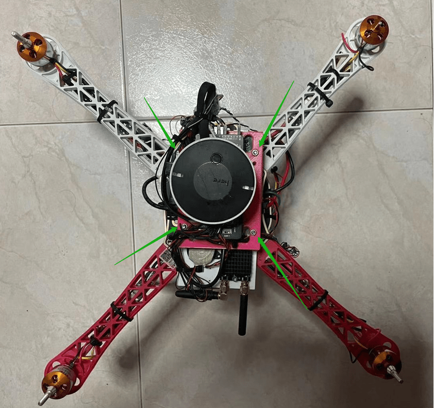
Screw holes pointed out by green arrows
To firmly affix the raspberry pi to the drone, we had to 3D printed stand that serves as an extra deck so that the Raspberrypi could be positioned a level below the Pixhawk controller. When we installed the raspberry pi on the new stand, we found that the screw holes printed were a little smaller than the M3 screws we intend to use to fasten the stand to the drone’s main body. Hence, we resorted to using drills to enlarge these holes.
After finishing the final assembly of the second drone, connecting the Pixhawk with the raspberry for release mechanism and tidying up the wire for the second drone. As we already have the tuning parameter for the first drone, we copied the firmware from the first drone which has been tuned extensively in term of PID and trimming and applied onto the second drone. The tuning parameter can be shared as both drones use the same frame and the same motor type. However, along the way we experience some problems. One of the major problems we experience is the Pixhawk not booting up after connecting the wire. The problem boils down to the power supply for the raspberry pi and Pixhawk not having the common ground, which causes the Pixhawk to detect abnormally in the serial port and refusing to boot up. This bug has wasted us 2 hours to find, the solution is relatively easy, simply unplug the shared power between Pixhawk and Raspberry Pi while leaving the RX/TX cable intact.
In the end, we did a simple calibration for the real flight happening tomorrow.
Final redesign of the release mechanism
The previous design of the mechanism proved rather successful. It was able to carry 100gs of weight. However, the trapdoor still leans downwards demonstrating weakness. Hence, we designed the 6th release mechanism that uses two trapdoors controlled by two motors. It works on the same premises as the previous design just with two doors now controlled by two motors.


We faced issues with the code where the trapdoor did not open when “landed”. After much tinkering, it worked.
5th Dec 2020
Actual flight day.
Today we test flight both drones at Old Holland Road. Firstly, we try the first drone which has a lower centre of gravity that makes it more stable. All the mode works perfectly on that drone since it was extensively tuned. This is not the case for the second drone as it has a relatively high centre of gravity. As such the manual takeoff is not very smooth and there are few times the drone hit the ground due to centre of gravity not in the middle. This problem can be overcome if fast take-off was attempted, basically, fast take-off refers to full throttle the drone during the take-off process and letting the Pixhawk compensate for the centre of gravity, not in the middle.
After achieving flight for both drones manually, we try to upload waypoint to the drone using mission planner, the first mission involves the drone flying in a square and land in the middle of the square autonomously based on GPS signal alone. Both drones manage to achieve this within 2 tries. There is a mishap where the battery shifted in one of the drones causing the Pixhawk to overcompensate in one direction and crashing the drone from a height of 5 meters. Luckily, the ground is soft (grass) and we only broke the landing gear which we foresee as a potential point of failure when we were preparing the day before.
After achieving autonomous flight, we next attempt to control 2 drones from the same terminal (Computer) using 2 mission planners to upload the waypoint, arming the drone and command it to take off and execute the mission. The mission was simple, take off and fly to the destination before returning and land at a different location without any human intervention. We were surprised to find out that the auto-take-off was way smoother than manual take-off and the mission was executed flawlessly on the first try.
After testing the mission multiple times in different direction and taking video for presentation, we wrap up the test and called it a day!
11th-12th Dec 2020: Exhibition Day
We won “Best Craftmanship” for our efforts in building a Dual Drone Delivery System. This proved that our “multi-drone delivery” could work. We pitched our idea to the NTU and Industry Judges. We could not be more proud of our achievement and seeing our efforts paid off. We would like to thank Kanesh B and Tony Gan for being our support pillars for this project. Also, this project would not have been possible with Dr Ho Sheng Yong and Han Yang.