Quadcopter

The quadcopter is a popular and reliable design which flies using four motorized propellers. The flight is balanced by allowing two propellers to rotate clockwise, and the other two to rotate counter-clockwise. This way, the four propellers can generate lift and thrust simultaneously.
Each motor speed can be adjusted to allow for flying controls. Pitching and rolling, which tilts the drone in any of the four horizontal directions, are achieved by increasing the speed of two motors, therefore increasing the lift of one side of the drone. A forward thrust is created in the direction of the tilt, propelling the drone forward. Yawing, which rotates the whole drone in the clockwise or counterclockwise direction, is achieved by decreasing or increasing the speed of diagonally opposite motors. A turning force will be generated in the desired direction.
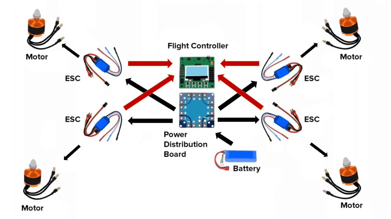
The quadcopter system is assembled from some basic components. For greater clarity, each component is enumerated below:
- Frame (not pictured): the frame, consisting of a center plate and four arms, holds the quadcopter together. It is lightweight and strong and often made of carbon fiber.
- Motors: the motors which drive the propellers are brushless DC motors, to rotate faster with the same amount of power provided. As with any conventional motor design, the shaft is rotated using magnets and fixed coils.
- Electronic speed controllers (ESCs): regulates the speed of each motor they are connected to. Also contains the battery eliminator circuit (BEC), which allows other components to be powered without direct connections to the battery.
- Power distribution board: houses connections to the battery. Regulates power flow and is often damaged first in an over-discharge situation.
- Battery: provides power to run the quadcopter. Almost exclusively LiPo (lithium-poliymer) based in drones today, to allow for rapid discharge.
- Flight controller: the brain of the drone, the flight controller contains the receiver module, the only connection from pilot to quadcopter in the drone frame. It interprets commands from the pilot to inform the ESCs to subsequently modify motor speeds. This component is also connected to the GPS module, sensors or other special features of the drone.
- Receiver and transmitter (not pictured): the pilot commands the drone by transmitting controls to the receiver antenna attached on the flight controller. This component also informs the pilot of the drone’s status as assessed by the flight controller.
Additionally, quadcopters will be equipped with other features for smoother flying and greater functionalities. These include GPS, accelerometers, gyroscopes and altimeters.
Package Load/Release Mechanism
The DroneInc drone relies on servo motors (also called servos) to load and release the package to be delivered. Servo motors are small electronic actuators which allows for precise control of angular or linear position. These devices are used inside our drone’s flying mechanism as well, but we added more motors to facilitate package delivery.

Servos are ideal for remote-controlled drones due to the large amount of torque they can generate given their small size. This is allowed by their compact mechanism, consisting only of a simple DC motor, control circuits and gears, which convert the generated work into useful work. The motor typically has a high RPM and small torque. Gears lower the RPM of the motor so that the torque generated becomes larger, allowing a small servo to lift even several kilograms of weight. This is remarkable given that typical servos work in the power range of 4.5 to 6 volts only.
Furthermore, modern servos work by an efficient control mechanism. A control wire contained in the servo receives pulses of electrical energy from a power source.

The control module monitors the position of the servo. Changing the frequency of the pulse instructs the servo to change in position, such as in the example below.

The payload for the DroneInc drone is loaded into a custom 3D-printed box with a lid, and this is attached with neodymium magnets to the bottom plate of the vehicle. When the switch controlling the servos on the remote control is closed, the servos rotate and the arm exerts a shear force on spacers attached to the box. This shear force separates the magnets on the box from the magnets on the vehicle, and the payload will be dropped from the drone.
